With my chair modded it was time to hook it up to an amplifier. I had a quick look on Amazon and eBay for cheap and used amps, but in the end decided to build one myself; it’s relatively straightforward and this way I would end up with something unique.
WARNING: THE FOLLOWING PROJECT USES MAINS ELECTRICITY WHICH CAN KILL OR SEVERELY INJURE, AND CAUSE DAMAGE TO PROPERTY. THOSE USING OR WORKING WITH ELECTRICITY MAY NOT BE THE ONLY ONES AT RISK – POOR ELECTRICAL INSTALLATIONS AND FAULTY ELECTRICAL APPLIANCES CAN LEAD TO FIRE, WHICH MAY ALSO CAUSE DEATH OR INJURY TO OTHERS. MOST OF THESE ACCIDENTS CAN BE AVOIDED BY CAREFUL PLANNING AND STRAIGHTFORWARD PRECAUTIONS. IF IN DOUBT CALL IN A PROFESSIONAL!
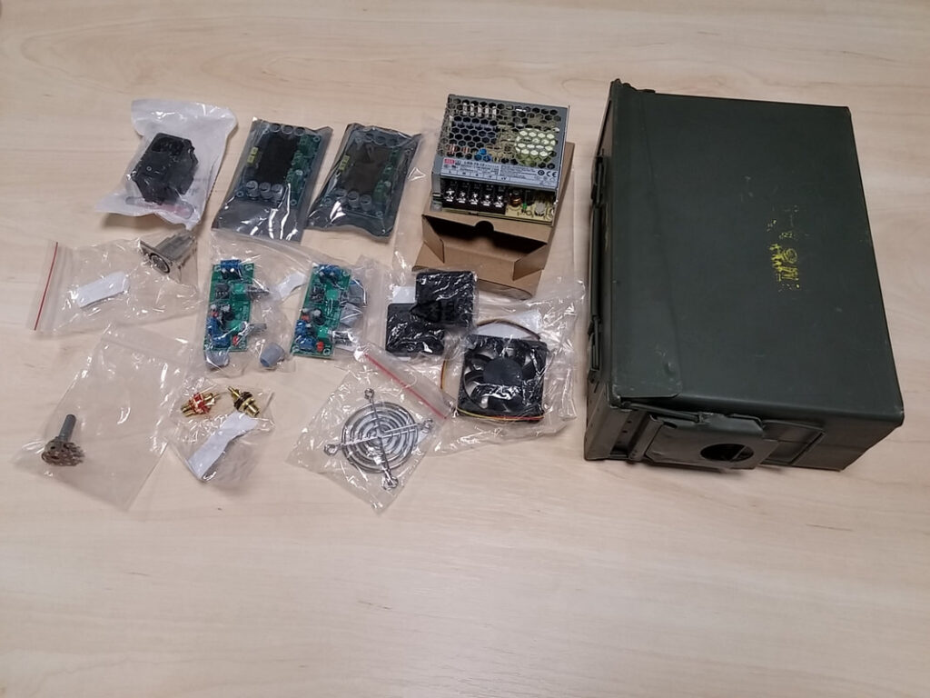
I decided to base my design around modules to greatly simplify the design. I used the following components:
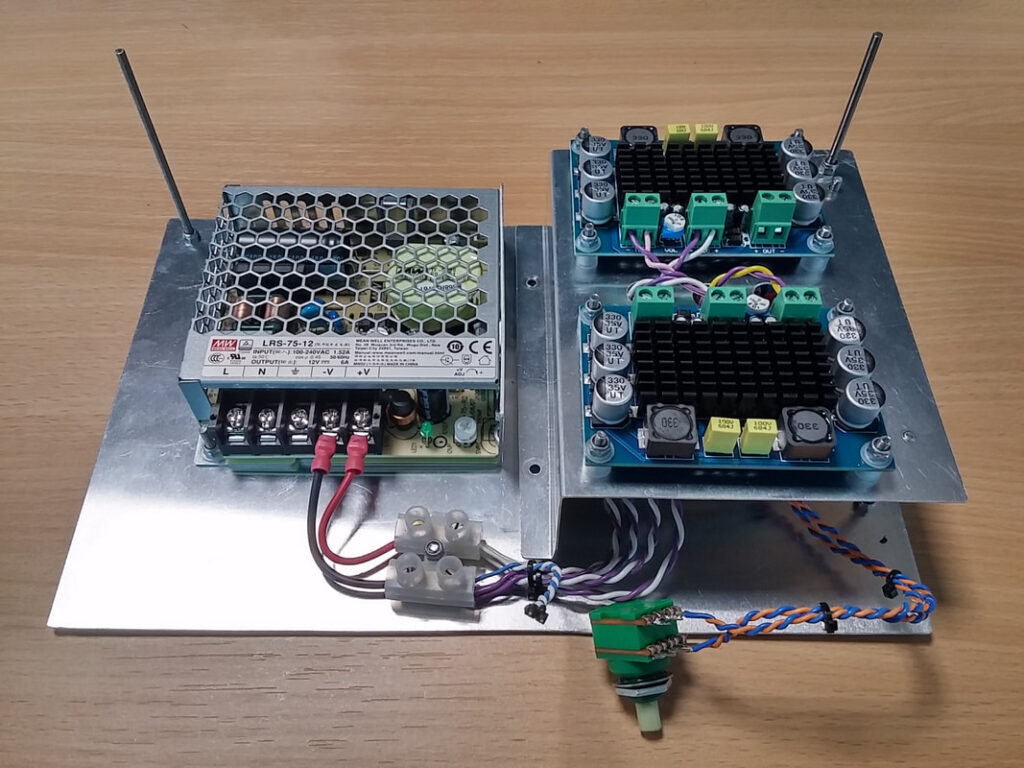
1x Mean Well LRS-75-12 12V 6A Switching Power Supply
2x TPA3116D2 Mono Amplifier Modules
2x NE5532 Subwoofer Preamp Modules
1x 60mm Fan
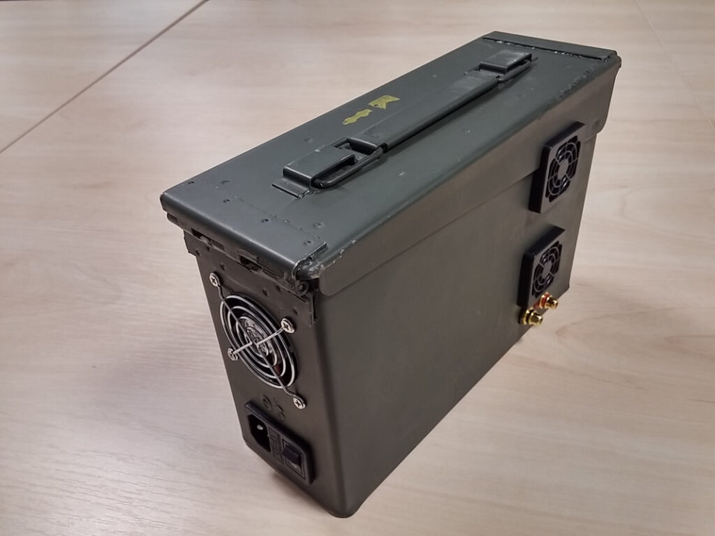
1x Switched and Fused IEC Inlet
1x 4-way Chassis Mount XLR Socket
2x 40mm Fan Covers
1x Pair Chassis Mount RCA Sockets
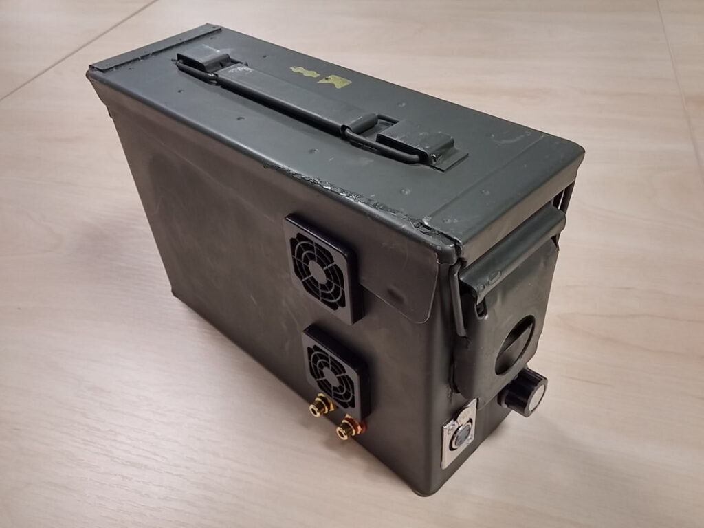
1x Ammo Tin (200 Cartridge, 7.62mm, M62)
Cable and Fasteners
I took a very conservative approach to the design of this amplifier. It was really important that the power supply be bought from a reputable supplier, and that it met or exceeded all relevant safety standards. I have successfully used Mean Well supplies in professional designs and they have yet to disappoint me, so stayed with this brand. I had no previous experience with the TPA3116D2 or the NE5532 based subwoofer preamps. My main concerns regarding this design were:
Electrical Safety
Effective heat management
Mains hum on the audio channels
After reading the TPA3116D2 datasheet, I was expecting up to 2x25WRMS with a 12V supply, as the modules are in PBTL (mono) mode. If needed, I could go as high as 2x31WRMS (with enough power budget left over to run everything else), if I adjusted the output of the LRS-75-12 to its maximum of 13.8V. I decided to mount everything on a metal chassis, in an earthed metal box to reduce or eliminate any EMI issues. Once the general layout had been planned, it was time to get on with construction…
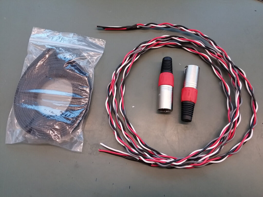
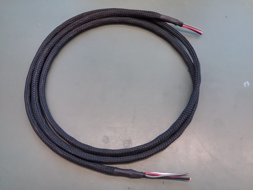
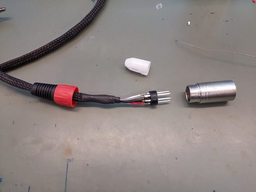
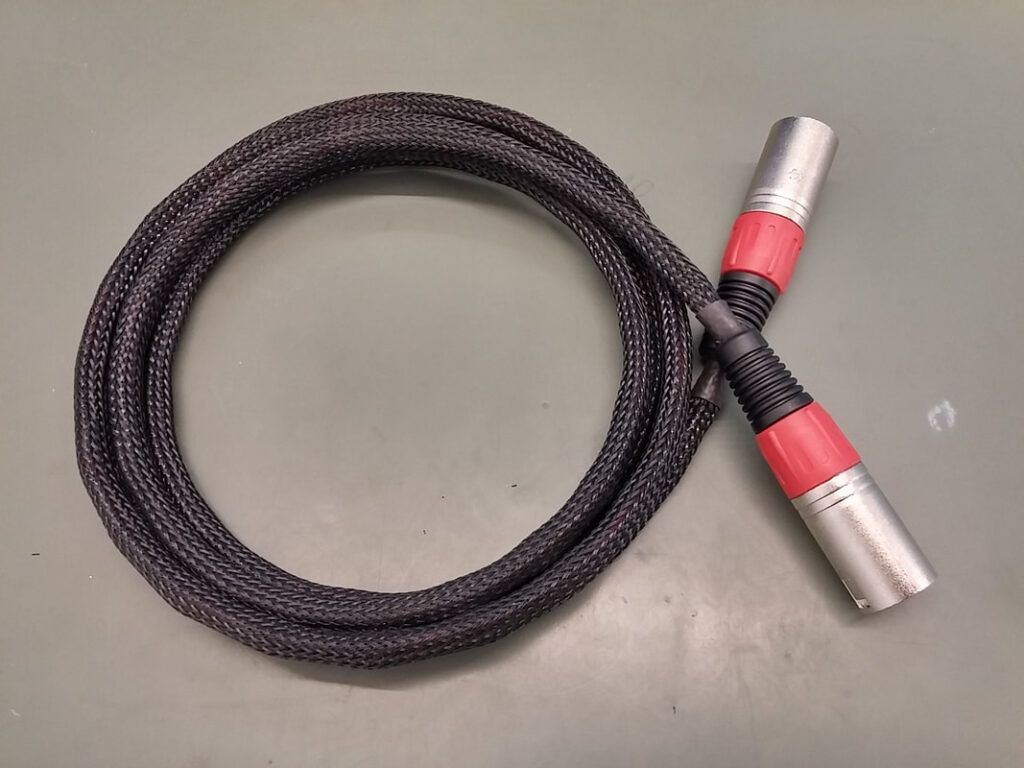
For whatever reason I couldn’t find a male to male 4-way XLR cable, so I made my own out of four lengths of 1mm^2 thinwall cable, and used a four strand round braid to weave it together. I had some cable braid left over from my Custom RCA Cables project (I made those for my Fiesta ST – check it out in the Vehicles section), and I bought a couple of XLR plugs to terminate the ends.
Weaving the cables together will eliminate crosstalk between pairs. Other advantages are an increase in rigidity and giving the cable bundle a regular shape. This allowed me to easily feed the cable through the braid, the regular shape improving the final appearance. The braid was fixed using heatshrink before the connectors were soldered on.
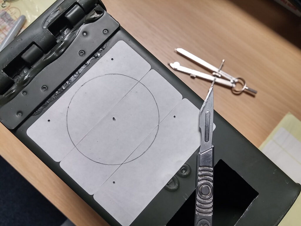
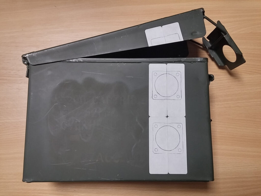
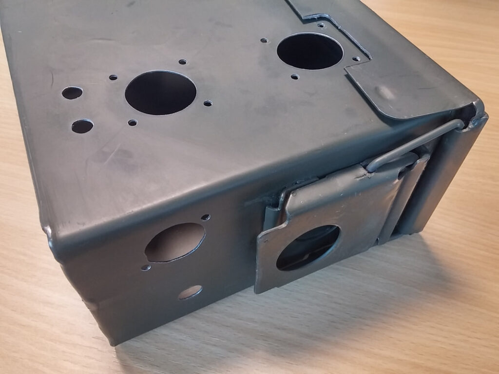
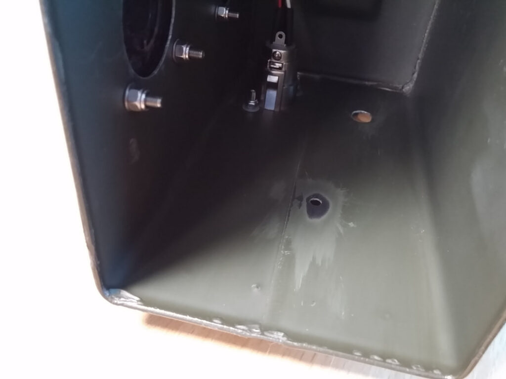
The ammo tin was bought on eBay and supplied with the yellow writing sprayed out, which may be why this one was cheaper than the other listings. Labels were applied to the box, the holes measured and drawn, the holes were cut out with a scalpel and finally marked on the paint with a permanent marker.
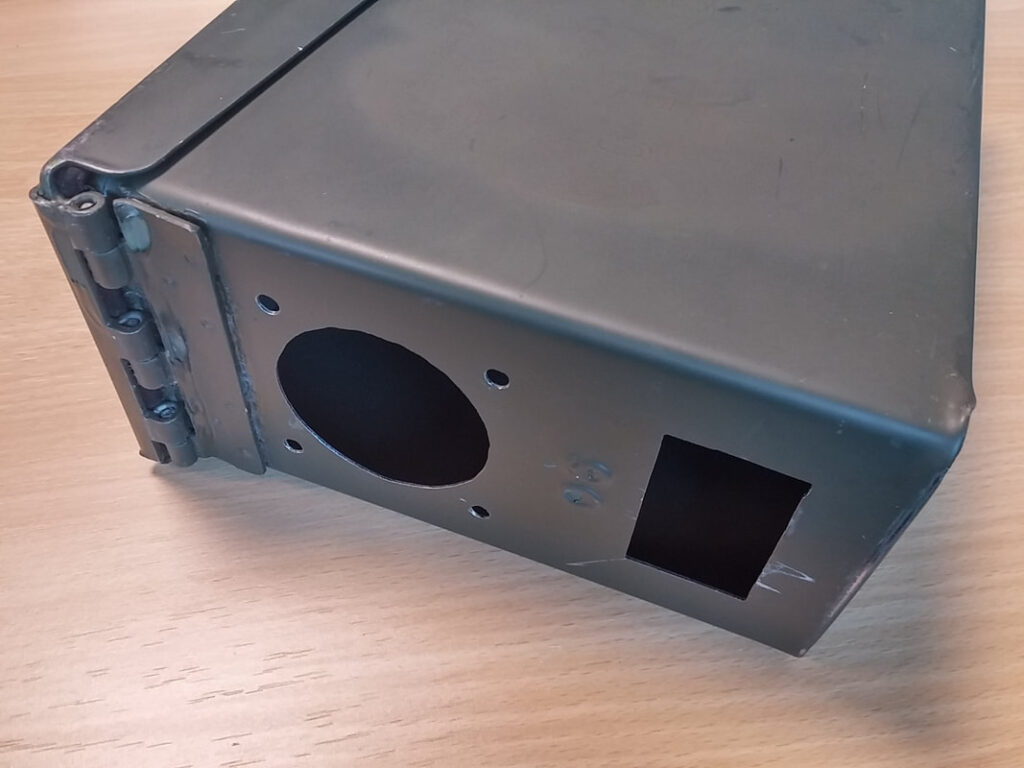
The ammo tin was tough to cut through! I first drilled numerous smaller holes in each larger hole, then cut out as much of the rest with a dremel and finally finished off with a half round file. I slipped a couple of times with the dremel during the rectangular cutout- fail…at least it’s on the back at the bottom…
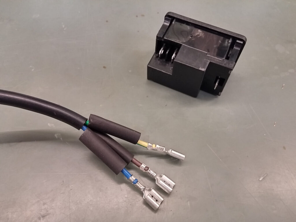
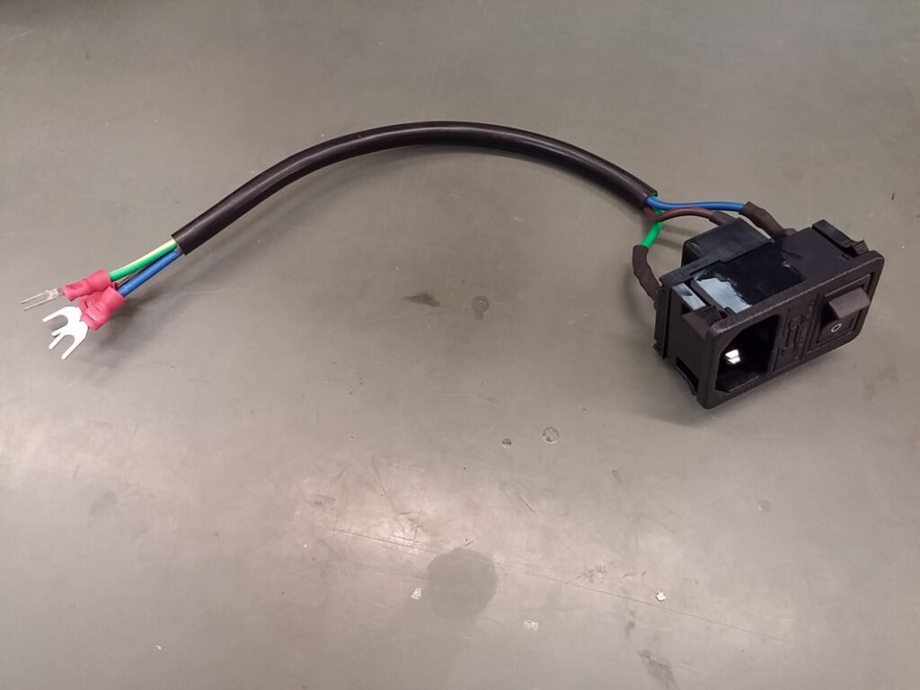
A lead was made for the IEC inlet out of some mains cable from a damaged mains lead that was being thrown away. Female spade terminals were crimped onto the IEC inlet side and Fork terminals were crimped onto the power supply inlet side. Heatshrink was slipped over the spade terminals and shrunk when the IEC inlet was connected.
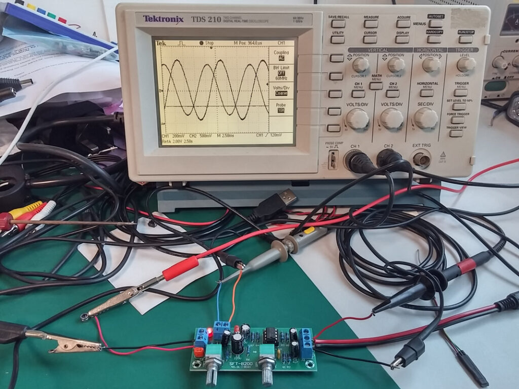
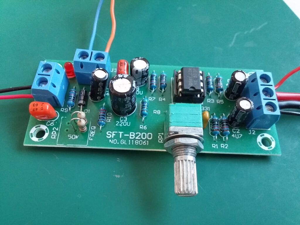
The NE5532 Subwoofer Preamp Module has adjustable gain (RP1) and cutoff frequency (RP2). I didn’t need the adjustable cutoff, so after some experimentation with a signal generator and oscilloscope I replaced RP2 with a couple of fixed resistors (1kΩ). The gain pot was also removed and two cables were soldered ready so that gain could be adjusted remotely.
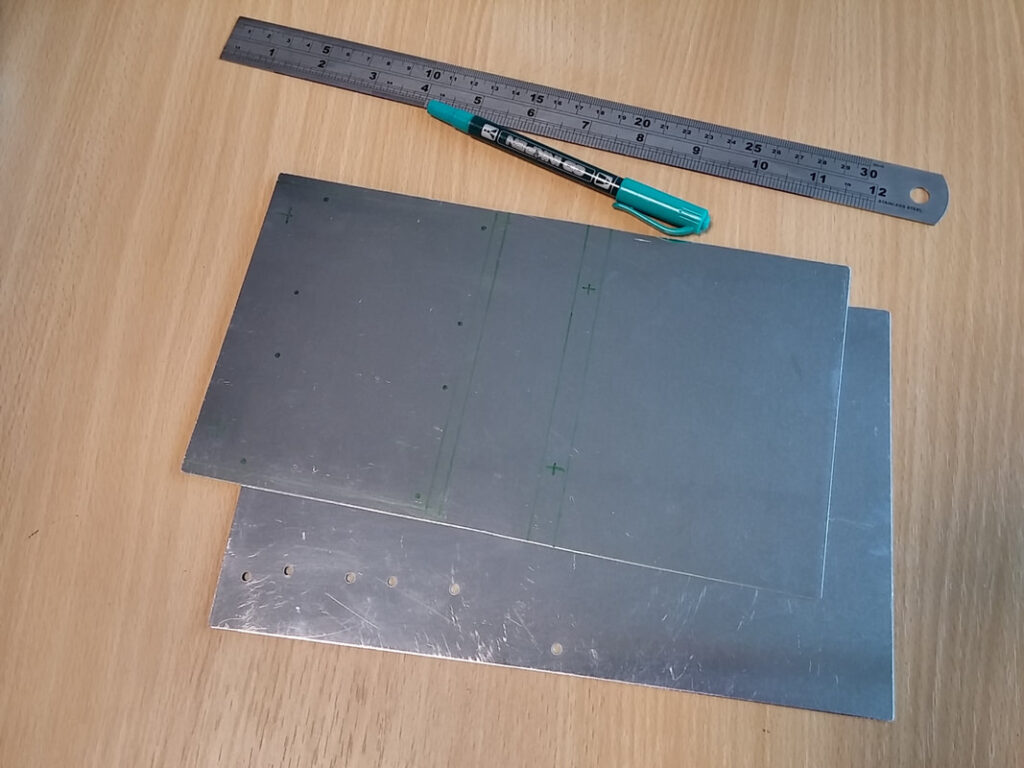
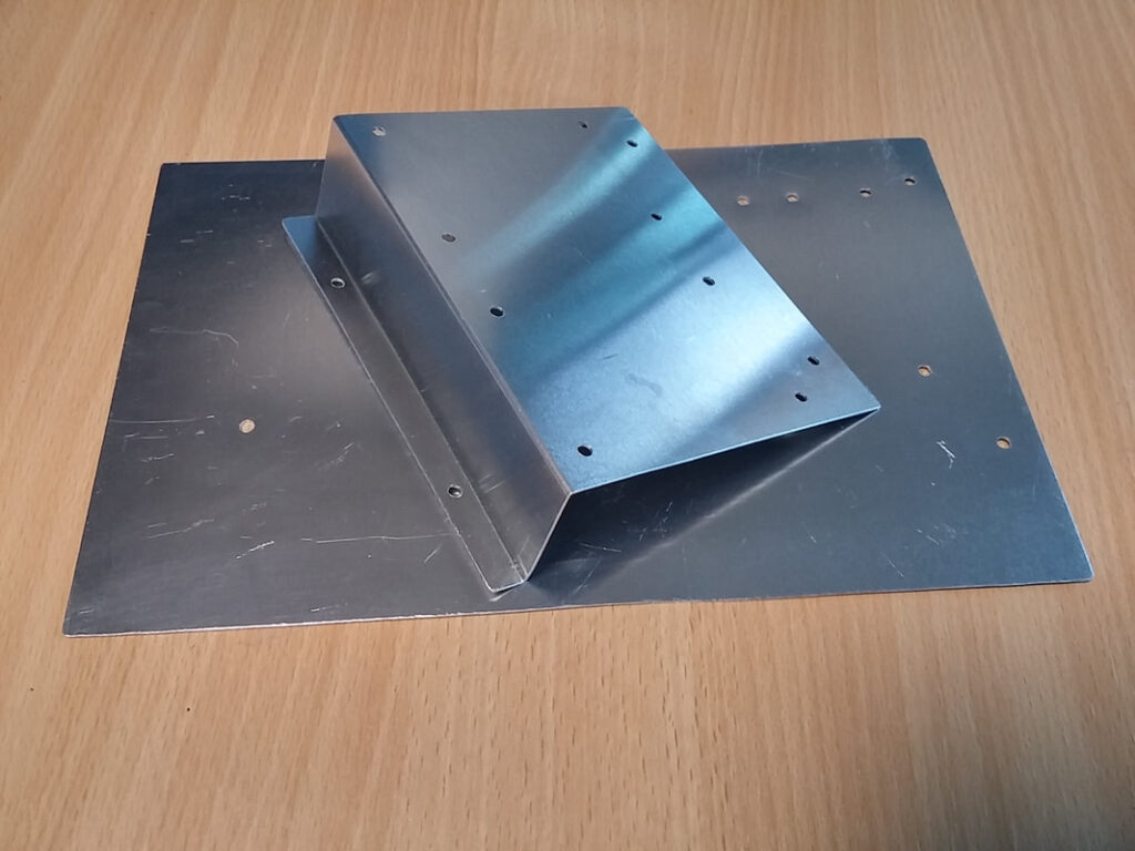
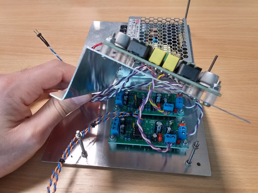
The chassis plate is a two-layer design made from 0.8mm aluminium sheet. The pieces were cut to size with a hacksaw and filed smooth. The flat sheets were first marked up, the holes then drilled and the upper plate bent to shape.
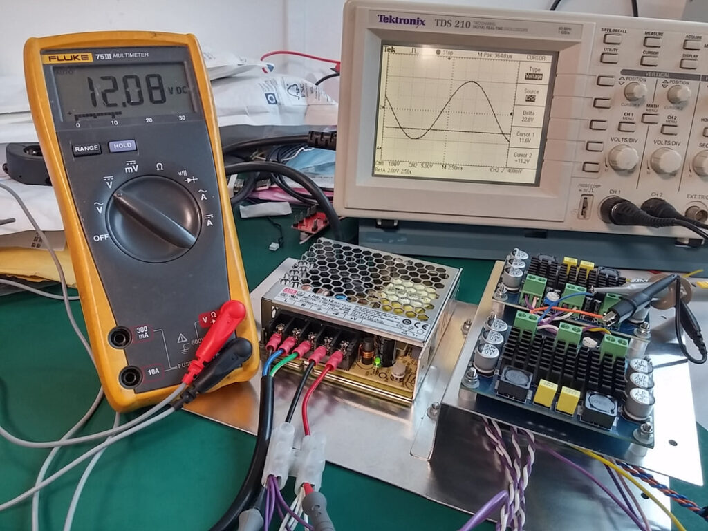
The system was bolted to the chassis plate and tested on the bench. Amplifier gain was first set to a very conservative 16.25WRMS/channel (1Vp-p input, 50Hz). Happy with the test, I continued working on the chassis, attaching the fan guards and stripping the paint from around the earth bonding point.
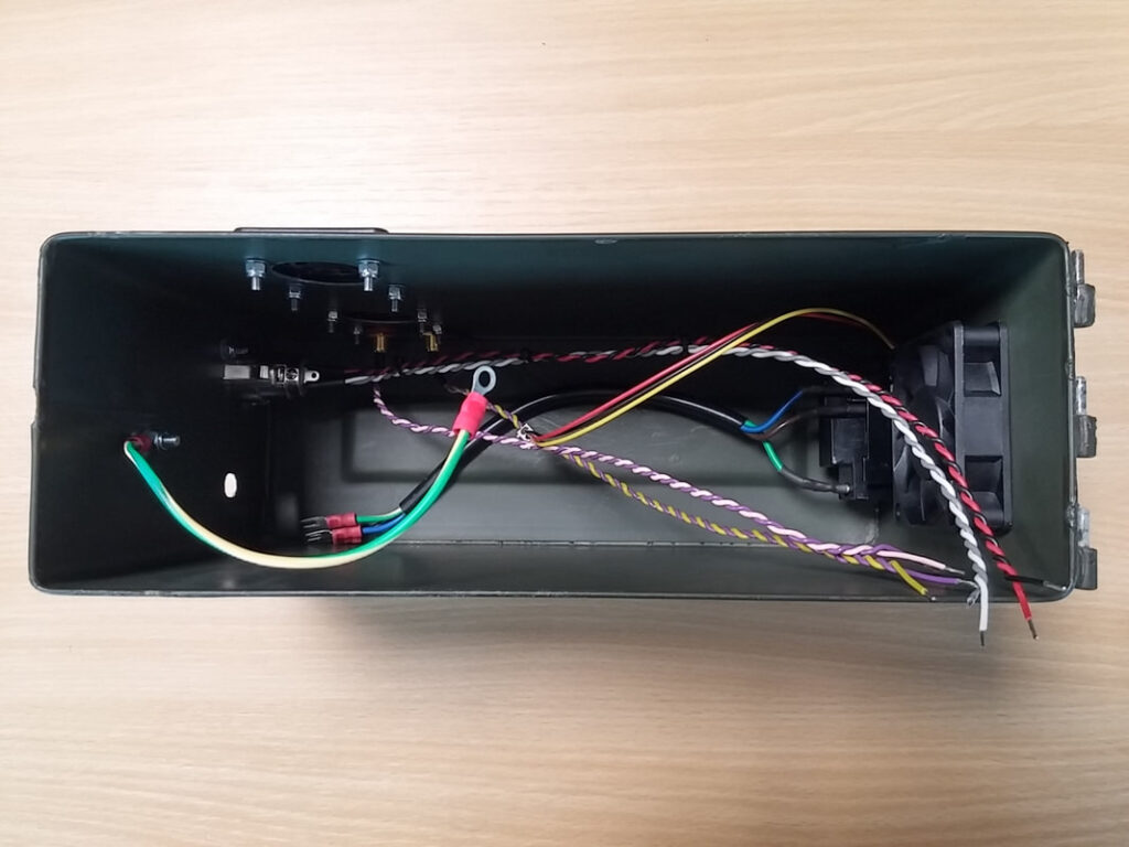
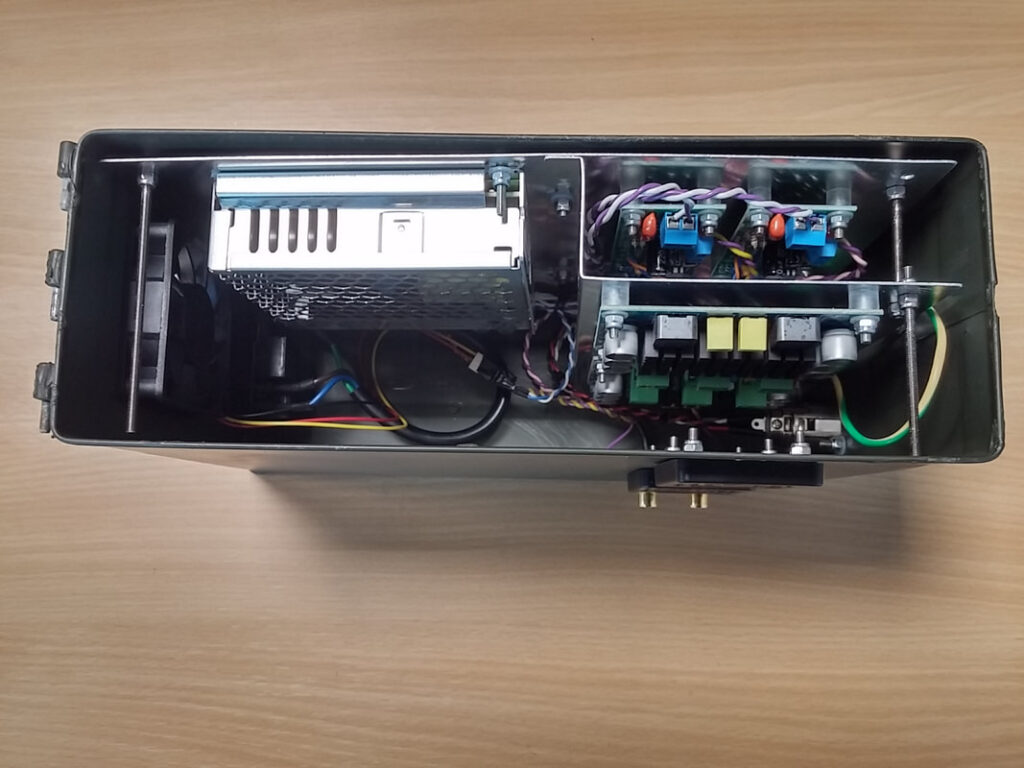
The leads for the connectors had to be long enough to be connected to the appropriate PCB with the chassis plate outside the ammo tin. The upper level had to be removed so that the RCA inputs could be screwed to the subwoofer preamps. I made the PCB spacers on a lathe out of some acrylic rod that I’ve had lying around for ages.
Two pieces of threaded rod prevent the plate from moving inside the ammo tin, and two secure the layers together. The green pot is used for gain control and is connected to both preamps. All cabling is twisted and is routed as neatly as possible. The fan is always on.
I am really pleased with this one; it’s simple, effective, and it looks cool. Being used to working with wood, plastic and softer metals, I found cutting the holes in the ammo tin to be a real challenge- it took me ages and I nearly broke one of my rotary tools in the process (my Black & Decker one started smoking, but I have had it for 15 years so I can’t complain). I was worried about mains hum coupling onto the output but I haven’t noticed any; this may be due to good layout, a quality power supply, or more likely a combination of the two. There have been no issues with heat- the fan moves a decent volume of air but makes a noticeable amount of noise. I increased the output power to 25WRMS/channel (1Vp-p input, 50Hz), and have found that this is more than enough for the Haptic Chair. Although the Dayton Audio TT25-8 manual lists power handling as 20WRMS per PUCK (so 2x40WRMS for my setup), I have found that I can hit the limit of excursion without the gain turned all the way up. I’m not sure if this is being caused by the TDS3116D2’s clipping, but referring back to the datasheet it is a possibility- I’ll have to get the ‘scope out at some point and have a look…