A NOTE ABOUT THE BUILD METHOD: This build predates my ownership of a 3D printer. Whilst I thoroughly enjoyed this build and learned lots from it, if I were to repeat this or something similar I would use FDM 3D printing to complete it.
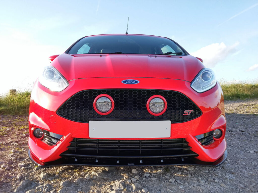
The modification of my grille with the addition of lights is one of my favourite mods. I wanted to add some rally-inspired driving lamps but was unhappy with everything that was currently available on the market. All of the driving lamps I considered looked obviously aftermarket, and disrupted the lines of the front end by bolting on in front of the grille, bonnet or bumper. We have seen grille lights on Mustangs since the first generation in the mid 60’s, so why don’t we see grille lights on other Fords? Mustang grille lights sit flush with the grille with the bezels molded in. The result is agressive but sleek looking lighting that is still aerodynamic and there is no impact on pedestrian safety.
I wanted to capture the look of rally, but also the sleek looks and intrinsic safety of Ford’s Mustang Grille design. I wanted my design to be road legal, capable of passing an MOT, and also made to a standard that would be theoretically capable of meeting CE/TÜV approval. I wanted to be able to fit the lights by cutting into the grille and bolting on, without the use of any adhesives, solvent welding or plastic welding.
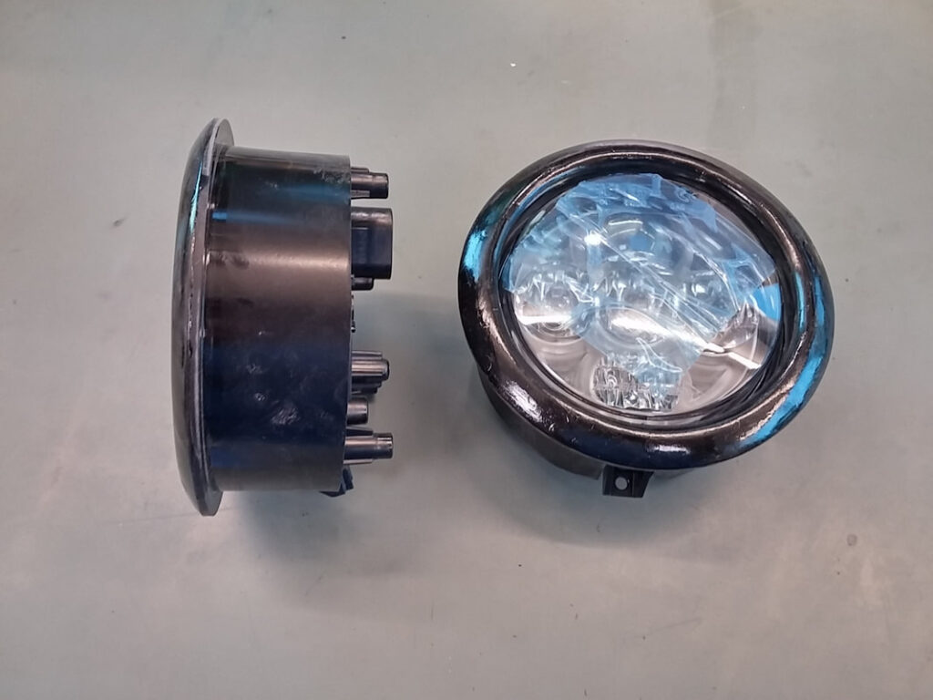
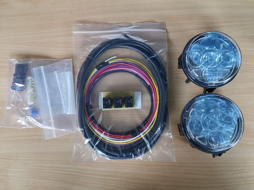
My design (registered design 6014752), is centred around a pair of JW Speaker 8415 Evolution LED headlights bought from Mobile Centre, and controlled by a custom wiring harness and relay board which I designed and made myself. Please read on for details of how I made the prototype. I would not be following this process again- I have generated CAD models now. If you are interested in using this design please contact me.
Wood is my go-to material when I need to make something [at time of writing]. For this project however, wood was out of the question. After considerable research, I decided that ABS plastic sheet would be ideal. Many plastics are a nightmare to paint, but ABS is used throughout the automotive industry so I would be able to have my bezels painted easily. ABS dissolves in acetone and turns back into solid ABS when the acetone evapourates; you can use it like a filler and a glue depending on how runny you make it. A potential issue with this method is that the solvent makes the plastic more prone to fail through Environmental Stress Cracking, although I don’t think that this will be an issue in my application.
The main focus of the design was the profile of the bezel, as this is the part that would be visible. I wasn’t sure how tall I wanted the round off or how wide I wanted the bezel, but it had to look balanced. Please read on to find out how I designed my prototype.
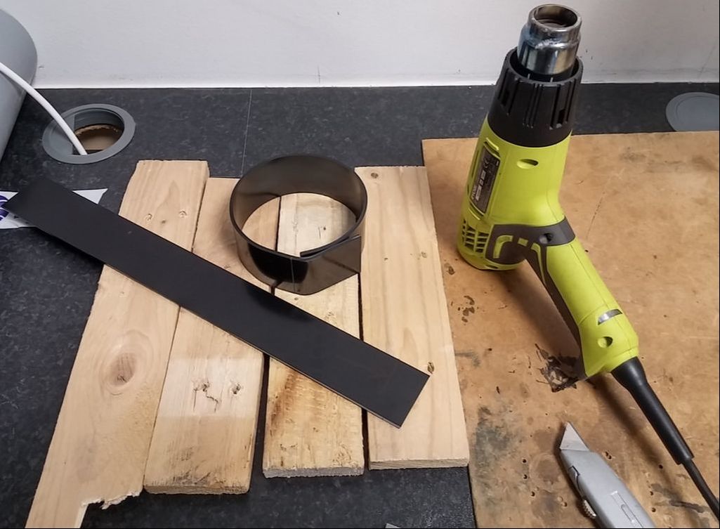
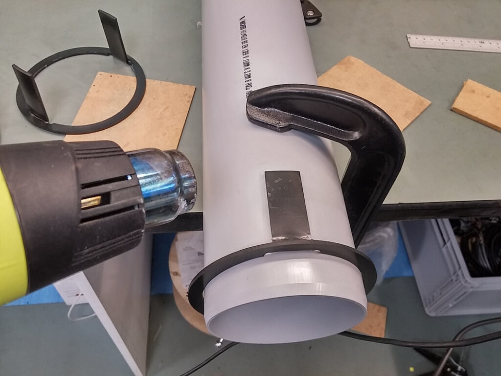
I first needed to make the body of the bezels that would hold the lighting units. I cut strips of ABS and heated and bent them round some soil pipe. As luck had it, this was pretty much exactly the right size I needed.
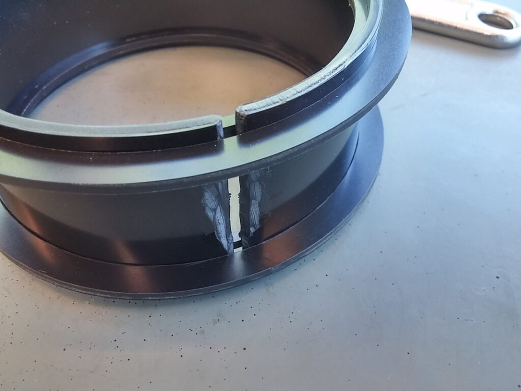
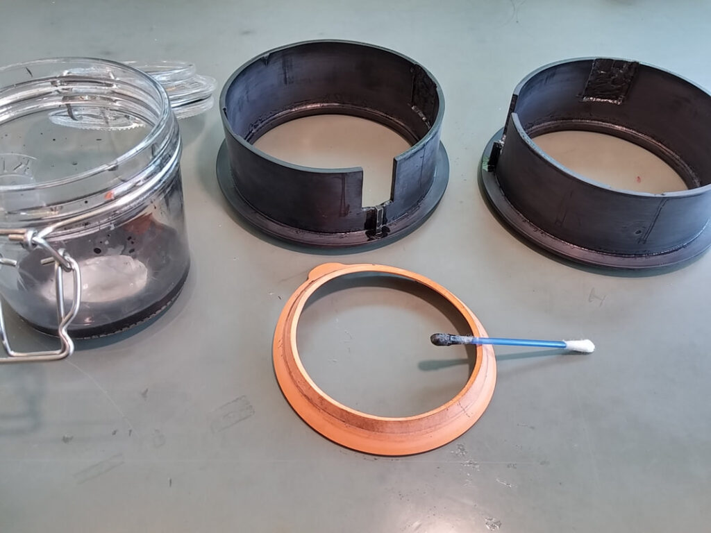
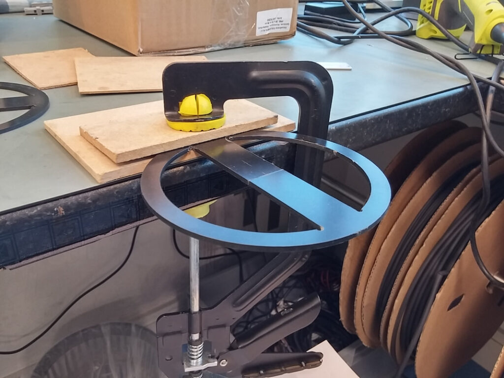
My colleague CNC cut some rings for me to go on the inside and outside of the bezels- more on why soon. I supported the bent sheet and heated it again gently, making the curve uniform. I tapered the edges that were going to be solvent welded to increase the surface area.
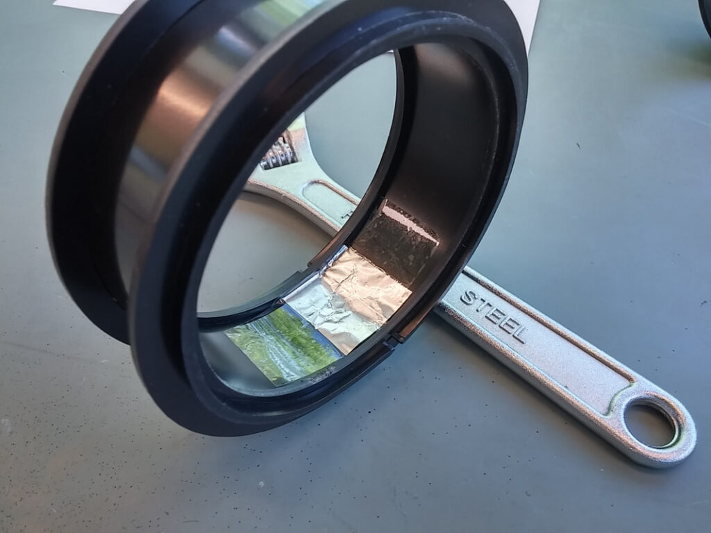
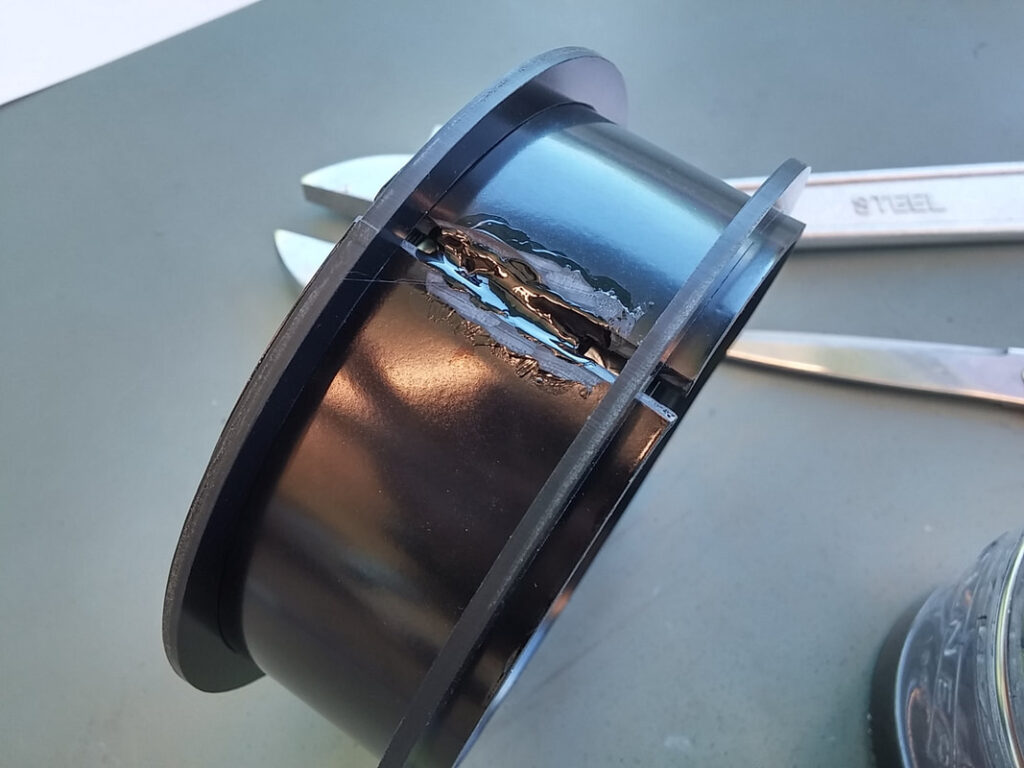
I taped some aluminium foil to the back of the joint. This allowed me to layer up the ABS gloop that I had made by dissolving ABS in Acetone. I found that if I put it on too thick it took exponentially longer to dry/set.
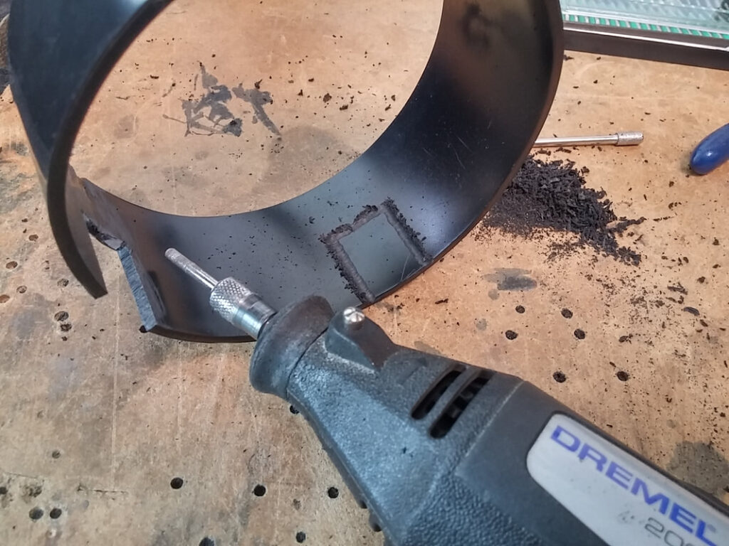
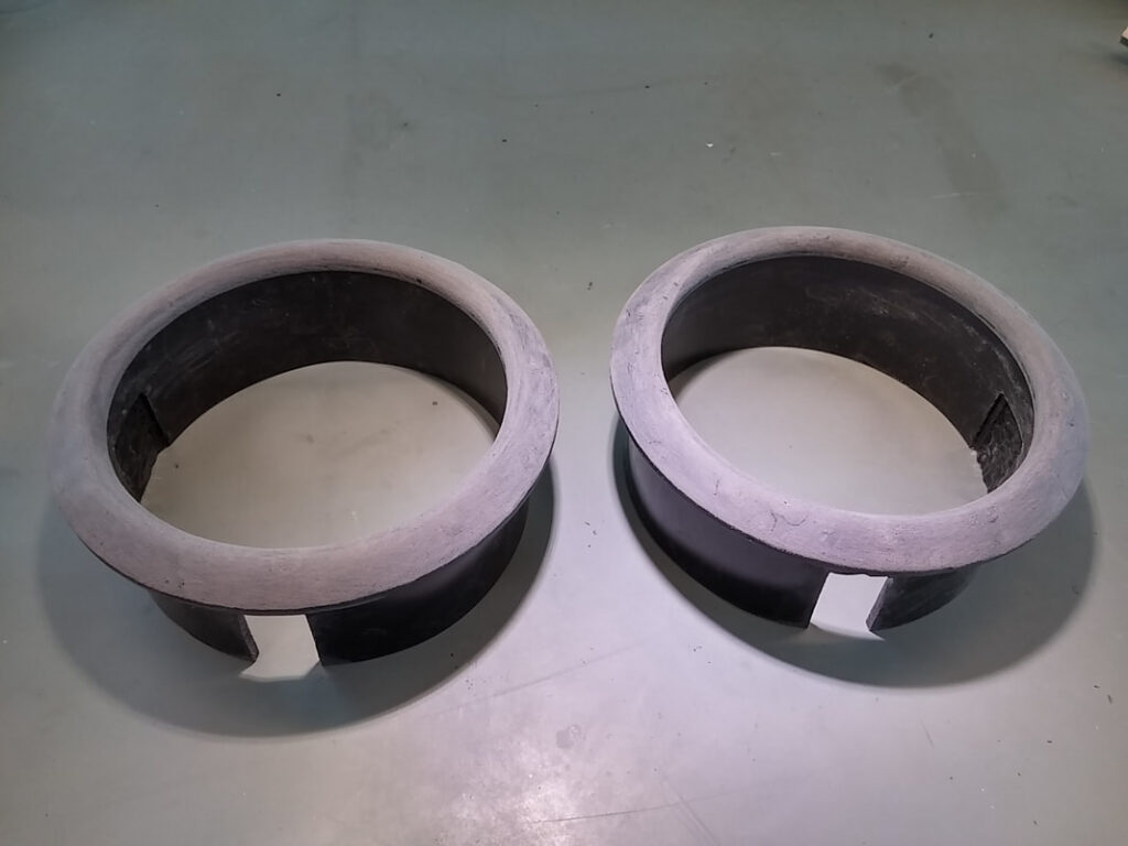
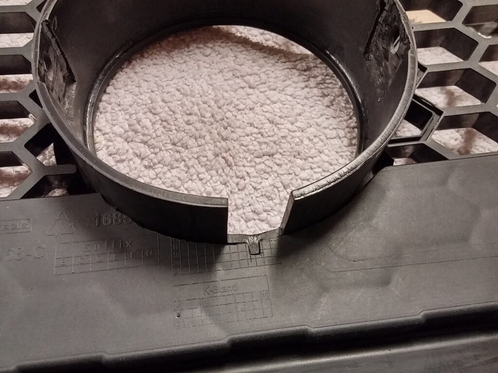
Once layered up and sanded back, I notched out for what I think is the tilt adjustment mount of the light. I marked out where the horizontal bolt mounts were.
The round profile needed to be squared off to allow the light to fit in, but the pockets that needed to be cut had to be blind- the lights needed to screw through the bezel and hold it in place.
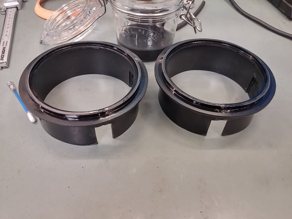
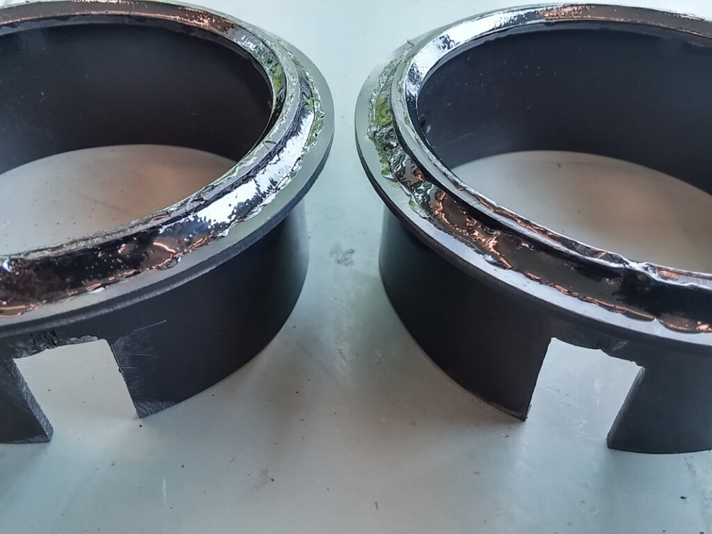
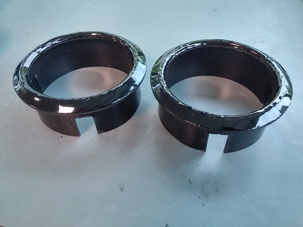
With the pockets cut, it was time to start work on the rounded profile of the bezel. The CNC cut rings form an inner and outer lip. The inner lip is required to hide the black plastic of the body, the outer lip is a flange that will hide fixings, keyways and any imperfections when cutting the hole. The rings were bonded using a thin solution of ABS dissolved in acetone.
The bezels were built up using a combination of gloopy and thin mixes of ABS dissolved in acetone. This was extremely tedious; I lost count of how many layers I did. It took ages- days and days of adding a layer every so often.
Keyway was added to the bezels to stop them rotating when fitted in the grille
Final test fit when I was happy with the overall shape of the profile.
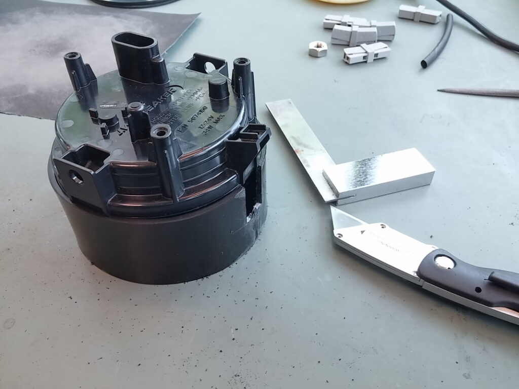
The mounting bracket was far more simple to make. My colleague CNC cut the shape out for me and I split the central tab in half. I bent them both up.
The tabs needed to follow the profile of the round body of the bezel, so they were heated and a curve was pressed into them. You can just about see the curve that has been pressed into the tabs in the bracket on the desk. The tabs were then trimmed to length and drilled.
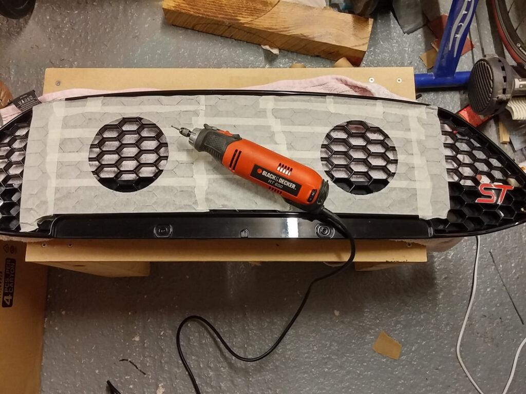
Some paper circles were cut and placed on the grille to help decide exactly where the lights were going to go. When the measurements had been made, the grille was removed from the car. The grille is straightforward to remove but the plastic tabs are so fragile- I broke one but it didn’t seem to matter. The grille was masked off to prevent scratches and the holes drawn with a compass and then cut out with a scalpel. I then cut the holes out with my rotary tool.
Test fit of one of the bezels with keyway shown locked in to prevent rotation.
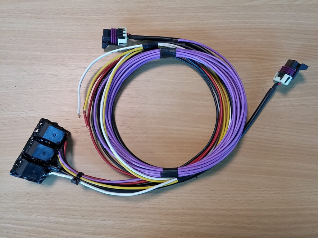
These are the components that comprise the wiring harness. All cable used is ISO6722-1 2011 compliant automotive cable. The Delphi connectors were supplied by Mobile Centre (Thanks Dave!). The PCB was designed by me. It has three automotive-grade relays and provides a remote enable in addition to switched power to dipped and main beam. The PCB was potted in hot melt glue for water resistance.
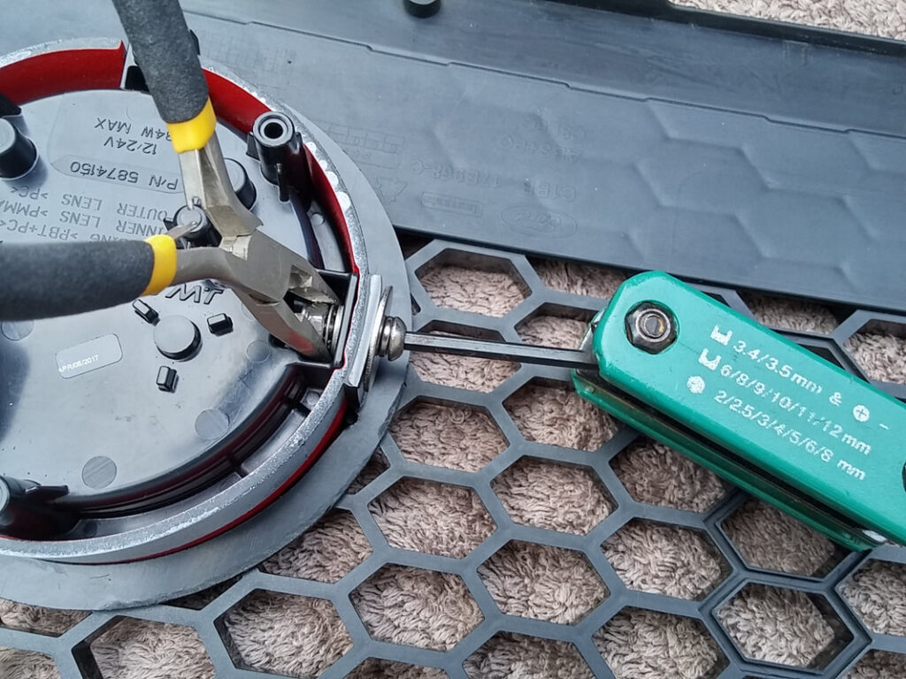
Fitting is fairly simple- slide the light into the bezel, slide the bezel through the grille matching up the key and keyway, slide on the mounting bracket from the back and bolt together. The light is held in place with two bolts. I made the holes slightly oversize to allow for some kind of allignment.
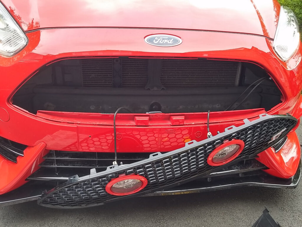
I’m so proud of this mod. In fact, I’m so proud of it, I put my name on it. I applied to register the design of the bezel and it was successfully granted in July 2017. In my opinion this modification looks about as close to OEM as possible, and really improves the look of the front end. Performance-wise, there is far more light to illuminate the way at night, however I have not been flashed by anyone, indicating to me that the increase in light output is not dazzling any other road users- Win.