I was really enjoying my Alpine SWE-815 active sub; the bass was great. It’s surprising actually, how much bass that little thing puts out, and I would highly recommend one as a simple bolt-on to improve any OEM sound system. Be warned- this game is a slippery slope…
A couple of months in and I was feeling that the door speakers needed to up their game. Maybe it was because the sub had loosened up a bit and was hitting harder, or maybe I was just looking for an excuse to mod my car again… Whatever the reason, I had decided that this was going to happen- it was just a case of how far I was willing to go with it. “If I change the speakers I might as well amp them up”, I thought. “If I amp them up I might need some soundproofing”, I wondered… “If it is worth doing, it’s worth overdoing”, a wise man from Mythbusters once said. I kept reminding myself why I bought the car:
It has 5 seats
It has reasonable boot space (to be fair almost anything has when you’re used to an MX-5)
It’s nippy
It’s fuel efficient when I need it to be
My install could not compromise the number of seats, or render the boot completely useless. It could not weigh too much as this would render buying into the ST badge pointless, and the efficiency of the install had to be as high as possible to minimise extra load on the alternator. Oh and no extra alternators or batteries. And lots of bass but not so much that the car shakes itself to pieces. OK I guess we’re not overdoing it then…
Car audio has been a subject of general interest to me for many years. Add to this my backgrounds in woodworking and engineering and I had a solid foundation of knowledge and skills for this project. This was my first proper install however, and I still had lots to figure out. I researched amplifiers, speakers, soundproofing, vibration damping and also car audio fabrication and installation techniques. The two following points were of great importance to me:
Quality of installation; I was not willing to cut corners which may jeapordise the long-term stability of the system; this was being built to last.
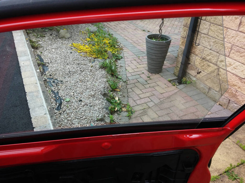
Safety; I was not willing to compromise the safety of myself, my passengers or other road users. All components used would conform to automotive (or equivalent) standards where relevant, and sufficient vibration damping would be used to minimize vibrations through the car, particularly the mirrors so that I could see reflections in them.
One minor issue concerned me- I had no idea how to strip my car out! I had taken the door trims off a couple of cars in the past, but that was it. I read and watched all I could find on dismantling my Fiesta… I didn’t find as much as I had hoped for but I was now as ready as I was ever going to be. My choice of components filtered down to:
Pioneer have been producing car audio solutions for 40 years, and Ford use Pioneer as an official supplier of optional extras for many cars in their range. Kenwood has been producing car audio solutions for around the same length of time as Pioneer, and also has OEM automotive deals including with Volkswagen AG. I felt that buying into these brands would be safe bets. To damp panel vibrations Silent Coat does what Dynamat does but costs a fraction of the price- this video by the Sound Deadening Shop sums it up nicely! Silent Coat is approved for automotive use. HydroWELD is sold as a material that is somewhat similar but cheaper than 3M Thinsulate. It is approved for automotive use, is hydrophobic, self-adhesive and is suitable for wet-side door installation. At the price I got it for I figured that even if the soundproofing performance wasn’t very good, if this test was anything to go by at least my car would always be warm…
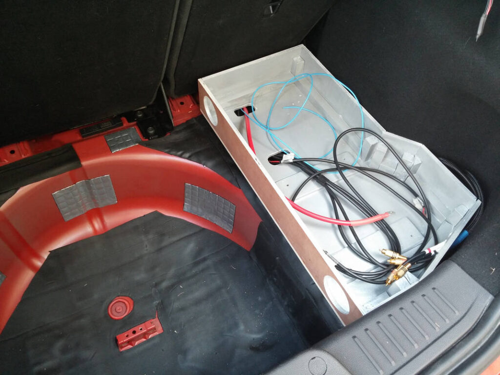
I decided to keep the OEM Sony head unit, if not to retain the stock look of the interior then because I wasn’t (and am still not) sold on the looks of the Double-DIN fascia adapter. I thought it a good idea to keep the OEM speaker wiring unmodified and run my own [ISO 6722-1: 2011 approved] cables instead. I planned to run tri-rated cable for power and ignition signal to the boot. Copious amounts of Tesa 56108 wiring loom tape would be used to tidy cables and help to prevent rattles. I would design and make a custom subwoofer enclosure in the spare wheel well (I pay for breakdown cover, I might as well take advantage of it…) and a custom boot build would protect all electronics and finish it off.
After over a month of planning and then procuring all of the required components and tools for the install, I waited for some good weather… I booked a couple of days off work for what would be a rather long weekend…
All of this preparation was done preceding me removing the interior of my car. I wanted everything prepared and ready to go so that the install would be as quick and painless as possible.
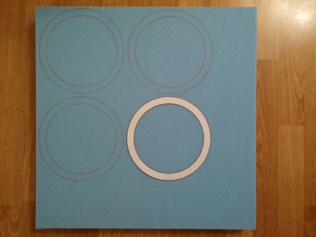
I had read about how using foam speaker rings to seal the speakers around the speaker opening of the panel increased mid-bass response, but couldn’t find a supplier for them in the UK. I contacted a couple of companies that cut foam to order but neither of them were able to perform interior cuts- I assume this is because they use bandsaws. I then saw this guy doing a perfect cutout of a gun in some Pelican Case foam using an electric breadknife and I went straight on eBay to buy one and some foam…
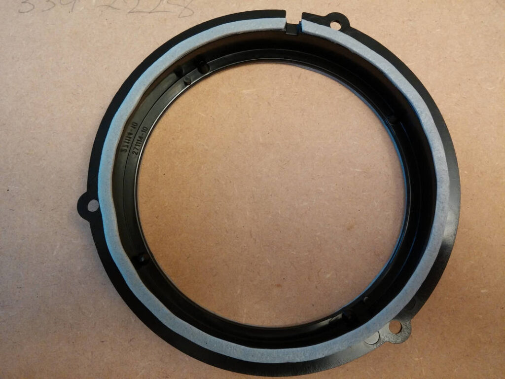
I made a template of the speaker rings out of card. I Measured the outside diameter of my Connects2 speaker adapters and made the foam rings a snug fit. The dimensions I used are as follows:
Outside Diameter: 193mm
Inside Diameter: 163mm
Wall Thickness: 15mm
Height: 50mm (2″ thick foam)
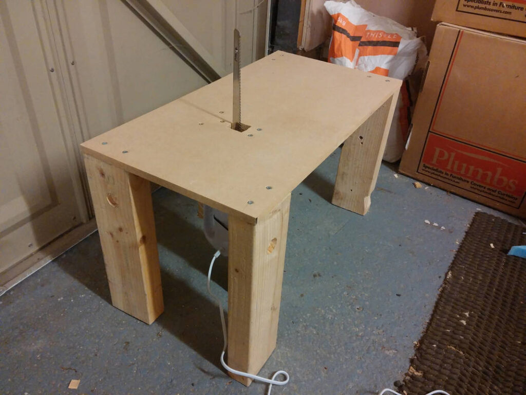
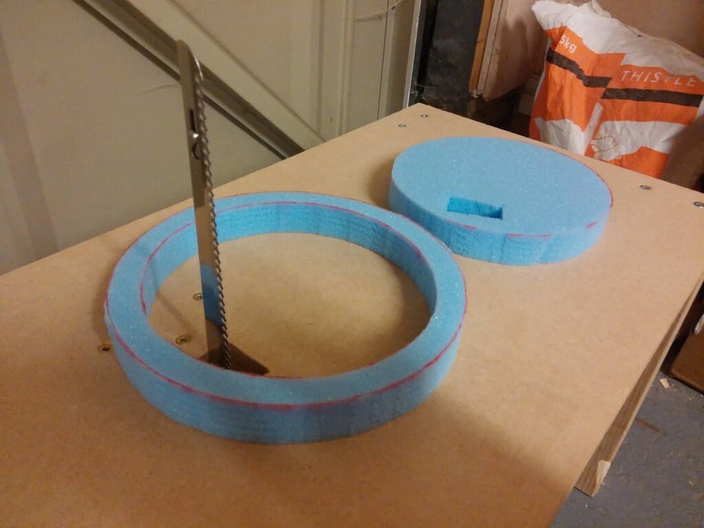
I made a table that held the knife in a vertical position with the trigger depressed permanently. I then wired a mains momentary foot switch in series to allow hands-free operation. I found that there was technique involved- if I tried to cut too quickly it ended up stretching the foam and cutting sloping edges. Good job I had some sample foam to learn with. Total cost of speaker rings: £20 + a few hours of messing around.
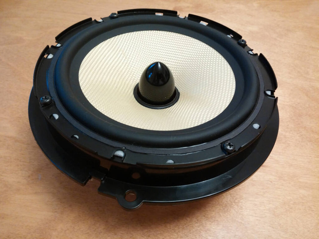
I added gaskets to both sides of the Connects2 speaker adapters; this ensured a good seal between the front and rear of the drivers. I used RS Components PVC Sealing Strip (205-0805). I then fitted the speakers.
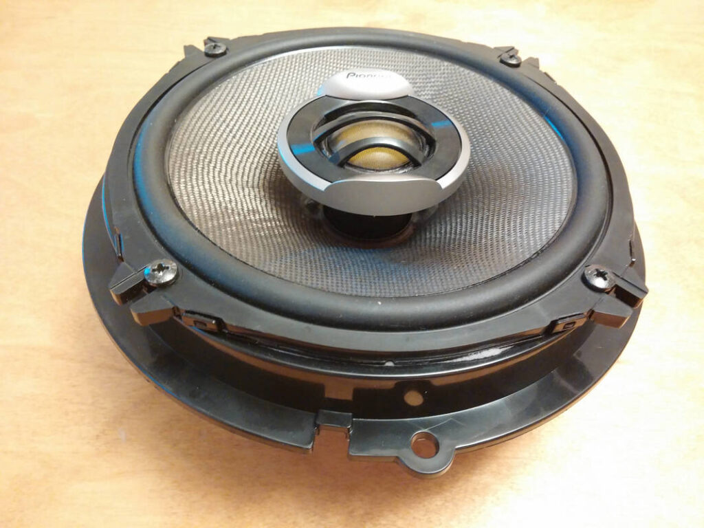
That bullet shaped thing is called a phase plug. The idea behind it is to extend the range of the speaker by halving the effective diameter of the woofer, which reflects different frequencies with more equal balance. Ideally these would have been fitted in the back too, but the standard rear speakers are coaxial and I was going for the stealth install look, so went for the coaxial versions.
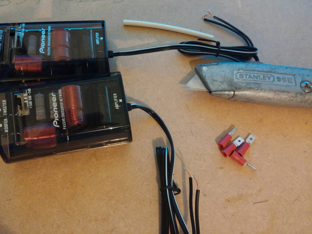
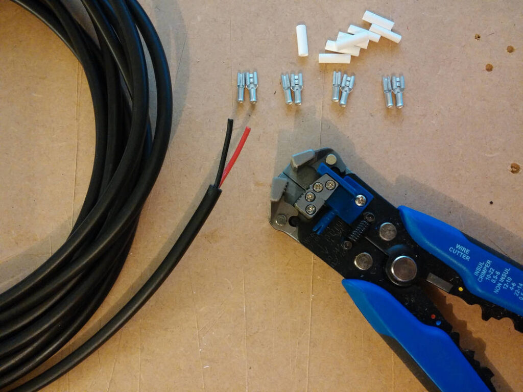
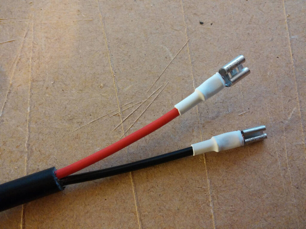
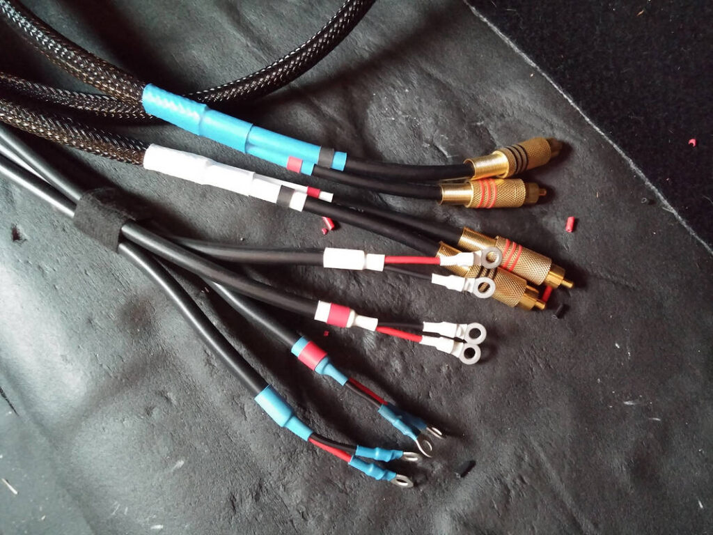
I roughly estimated how long I needed the speaker cables to be, then added ~1m to each just to be safe. The cables were labeled as they were all different lengths. Only one end of each cable was prepared- I was going to trim them to length after the install… The crimp sizes are standard speaker connectors, and are as follows:
Positive: Female Spade, 4.8mm
Negative:Female Spade, 2.8mm
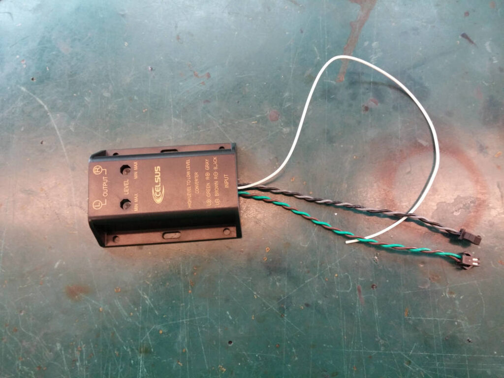
Crimps were added to the crossovers for the front component speakers, and the speaker inputs of the Line Output Converters were paired and JST SM male connectors added to allow for easy replacement down the line if required.
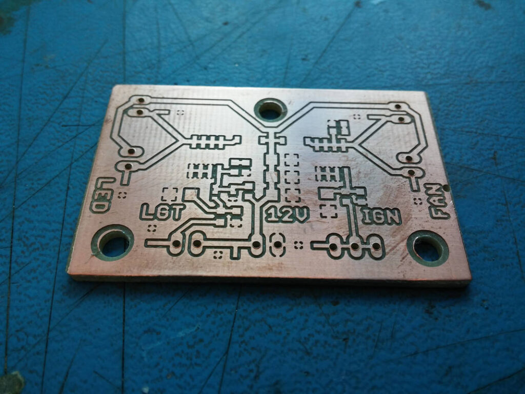
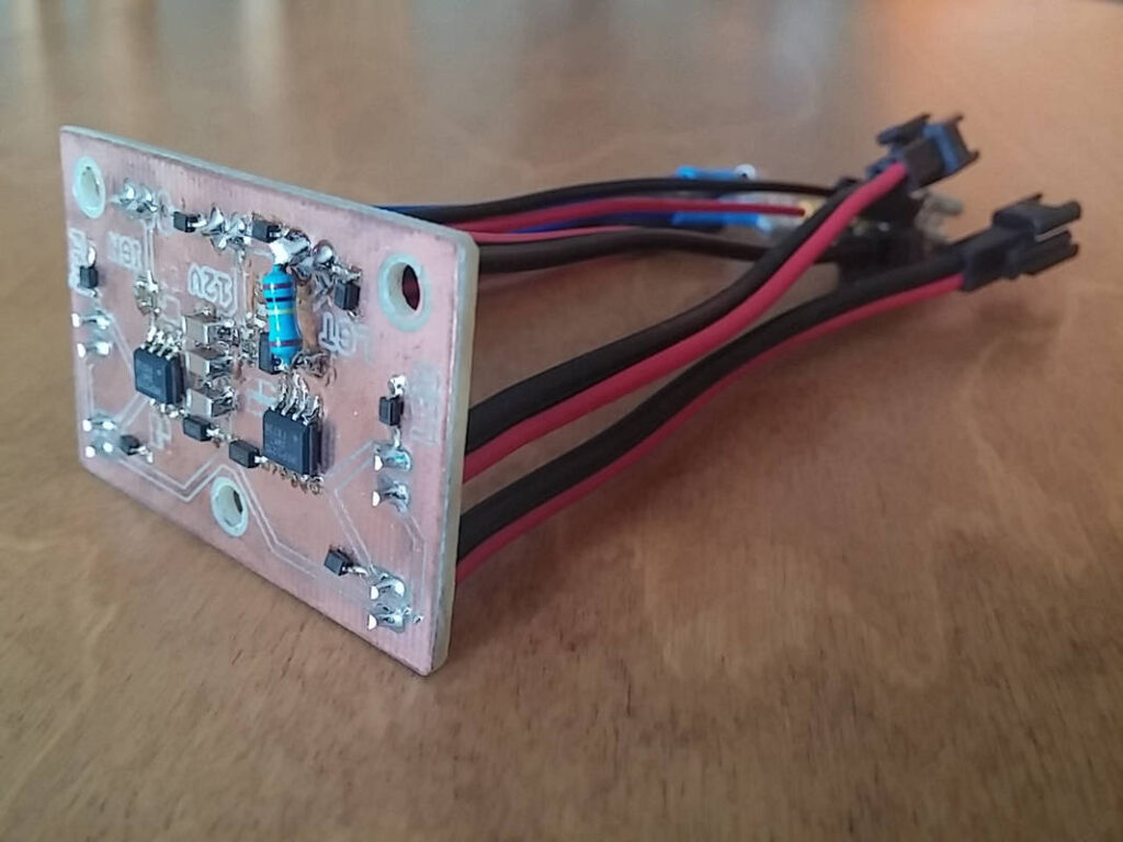
I made a simple PCB to control the electronics in my boot:
Cooling fans that switch on with the amplifier (Ignition)
Boot build lighting that switch on with the boot light
The PCB has its own fuse and draws power from the main boot supply cable.
I also made the amplifier cabinet that the PCB is housed in and the 10″ subwoofer enclosure. Please see my separate build pages for more information about these.
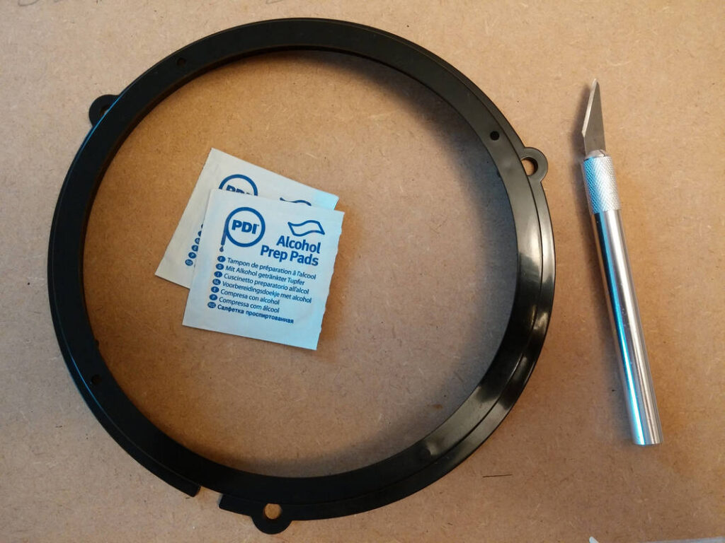
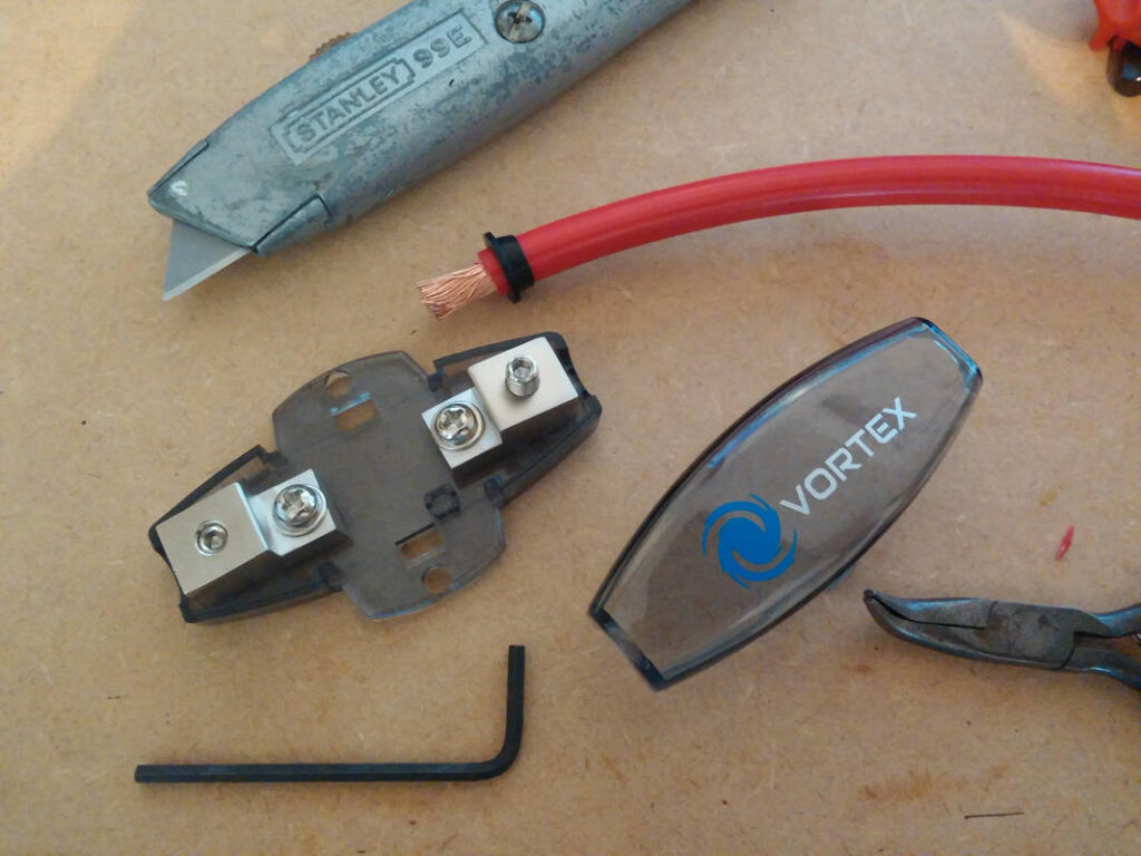
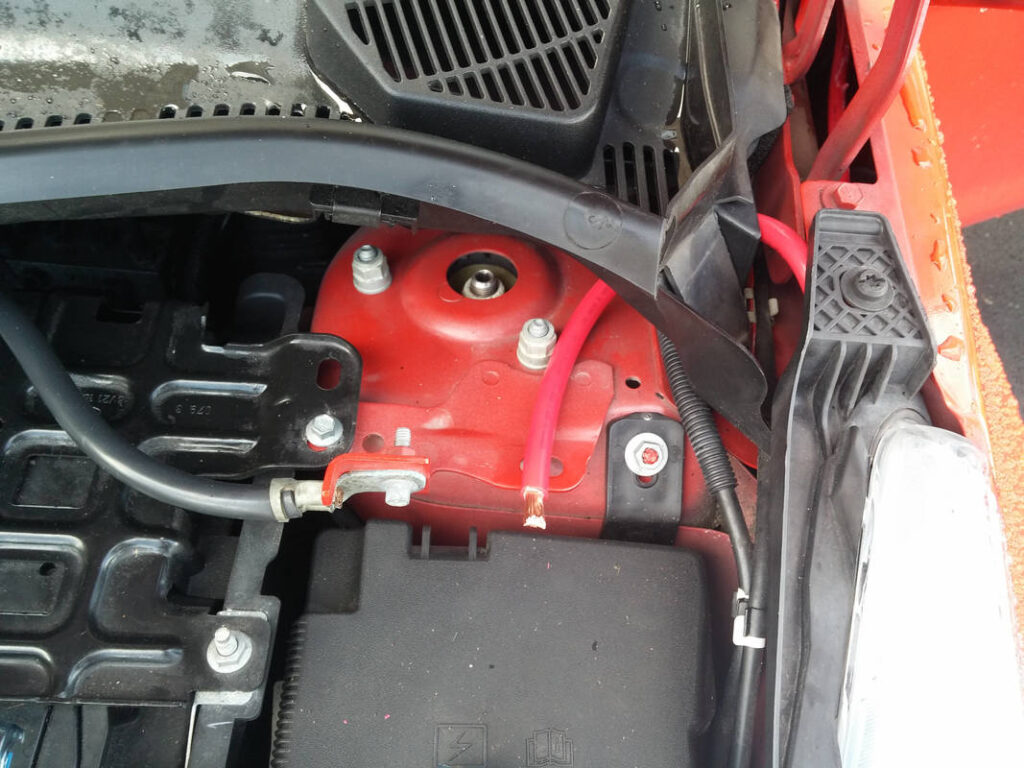
Last but not least… Modifying the blanking plate to accept a grommet (Pro Power 1475717), so that I could pass my power cable into my car with no leaks. This video is where I got the cable routing idea from. I’m not sure what the blanking plate is for, but I don’t have electric folding mirrors so I guess it may have something to do with that. The grommet was fitted in the blanking plate and will provide protection to IP67, but it will also prevent the cable insulation from rubbing against the blanking plate and wearing through.
With all components procured, all prep complete and the weather forecast as good as it was ever going to be, I booked a couple of days off work and my long weekend began…
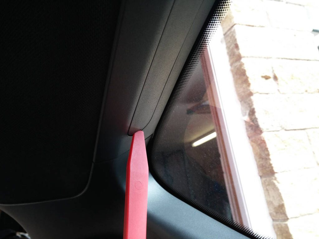
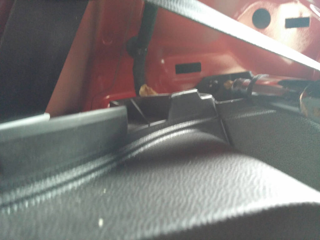
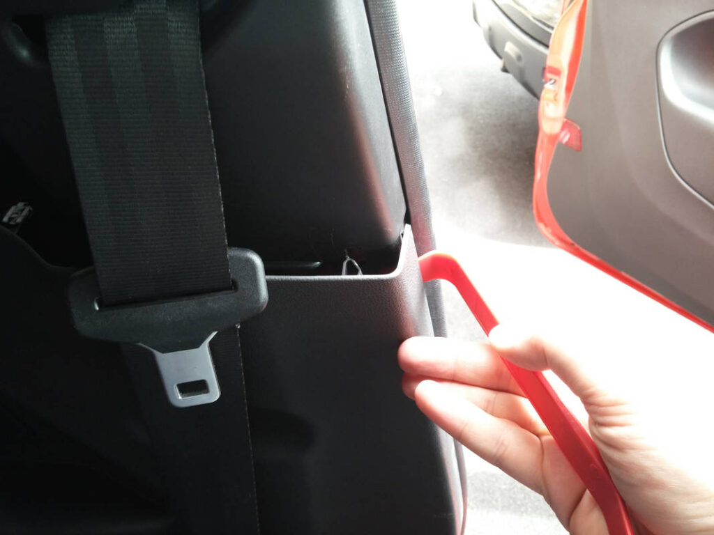
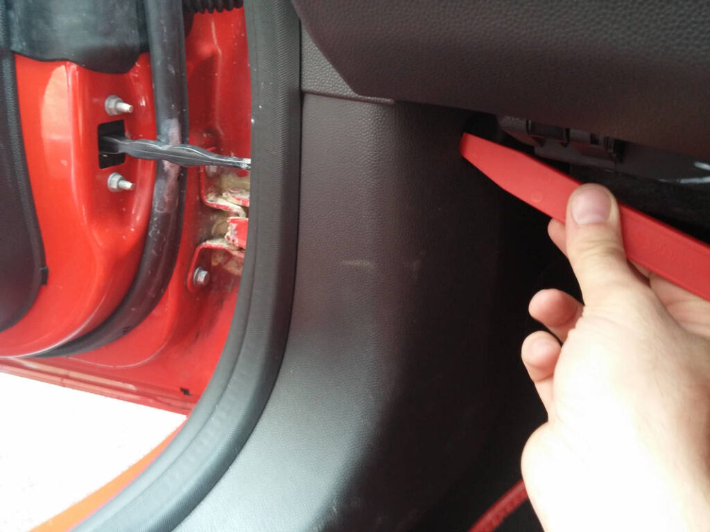
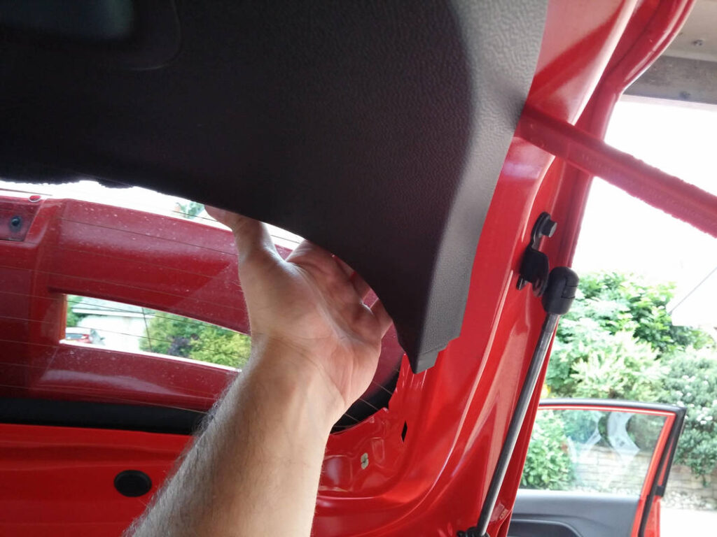
I started at the back. To remove the upper boot trim panel, I first had to pop out the lower part of the C pillar trim panel.
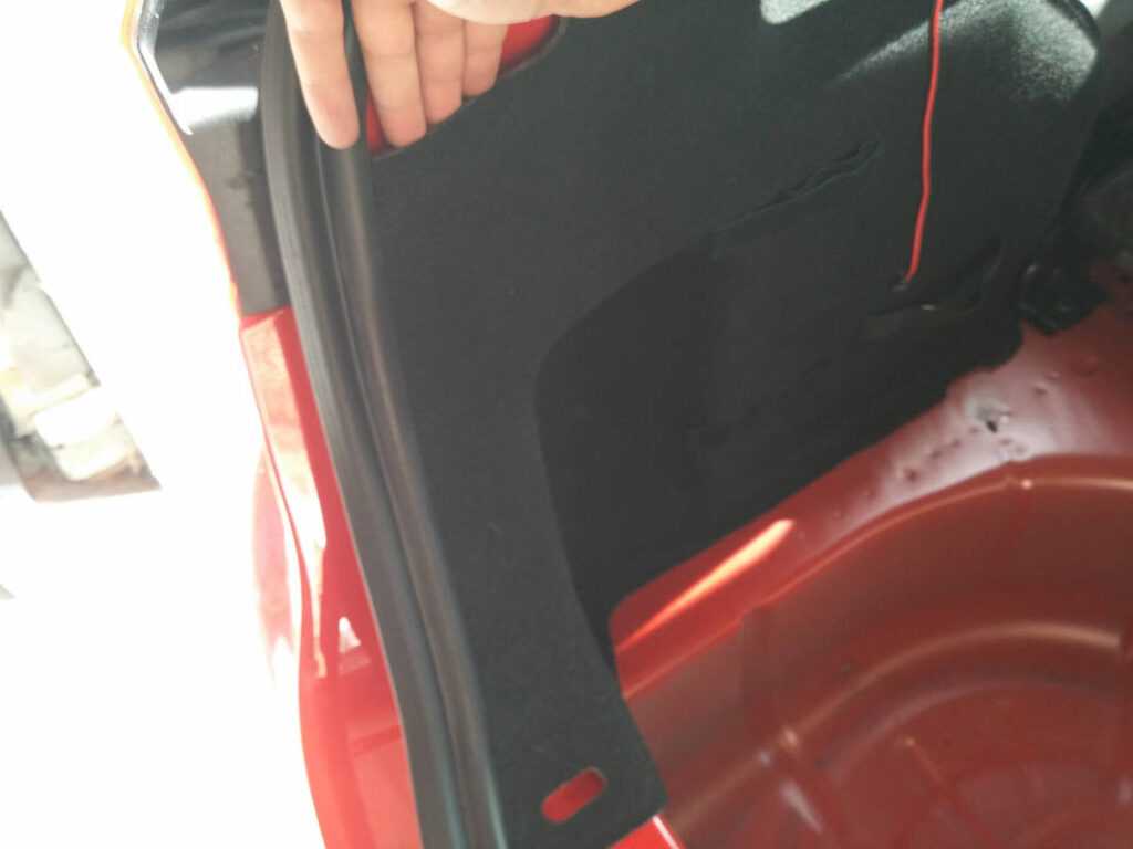
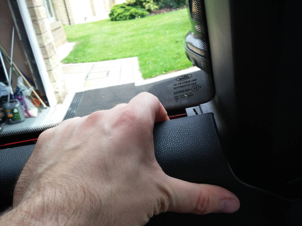
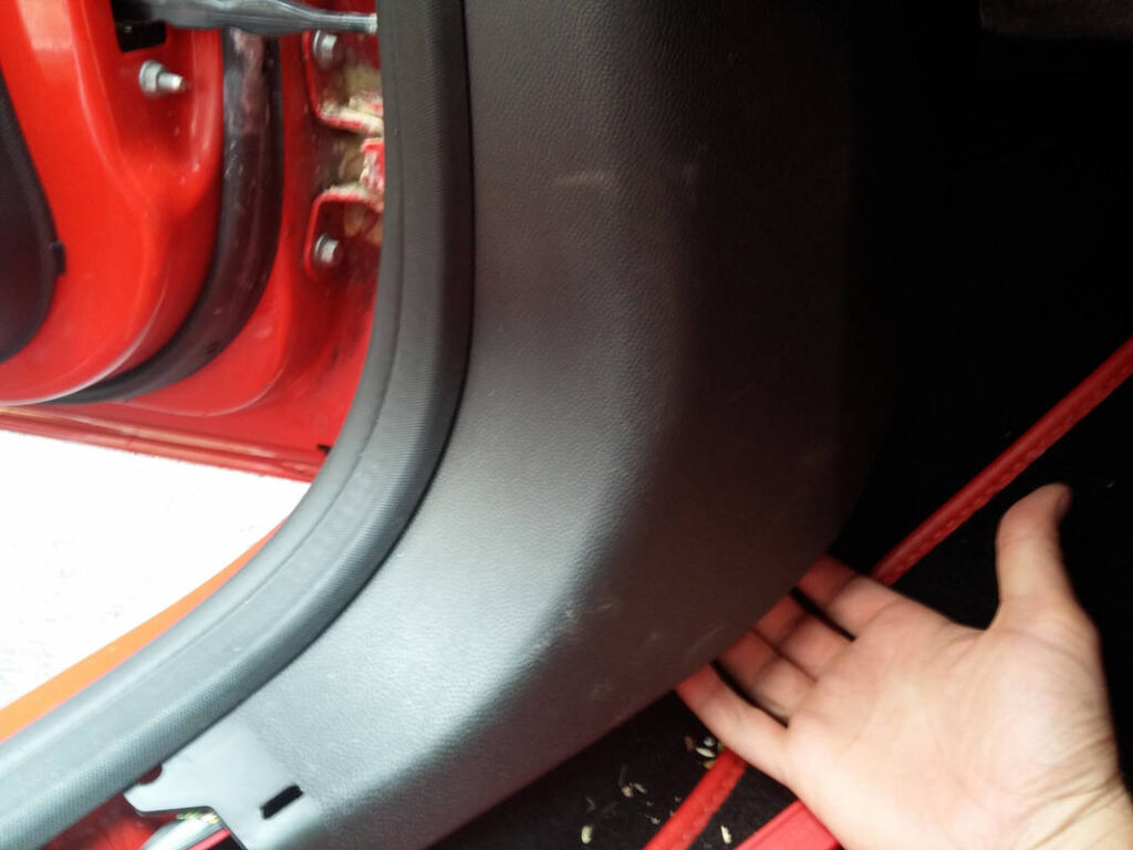
The upper boot trim panel was eased around the rubber seal and the pulled towards the front of the car to unclip the rear retaining clips. I then reached around and pulled towards the rear, and then finally upwards to unclip the remaining clips. I repeated this on the other side.
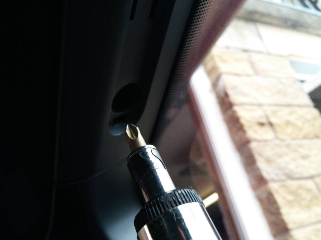
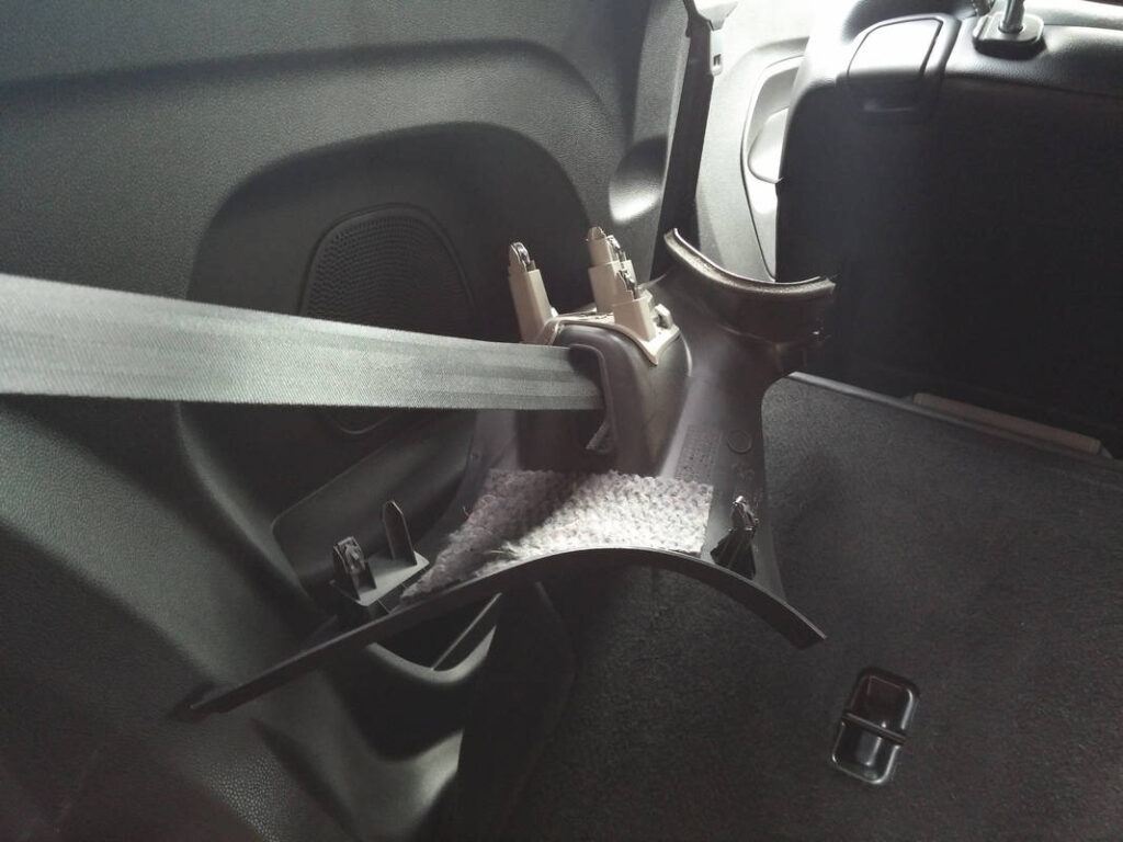
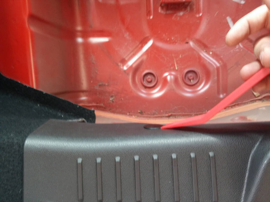
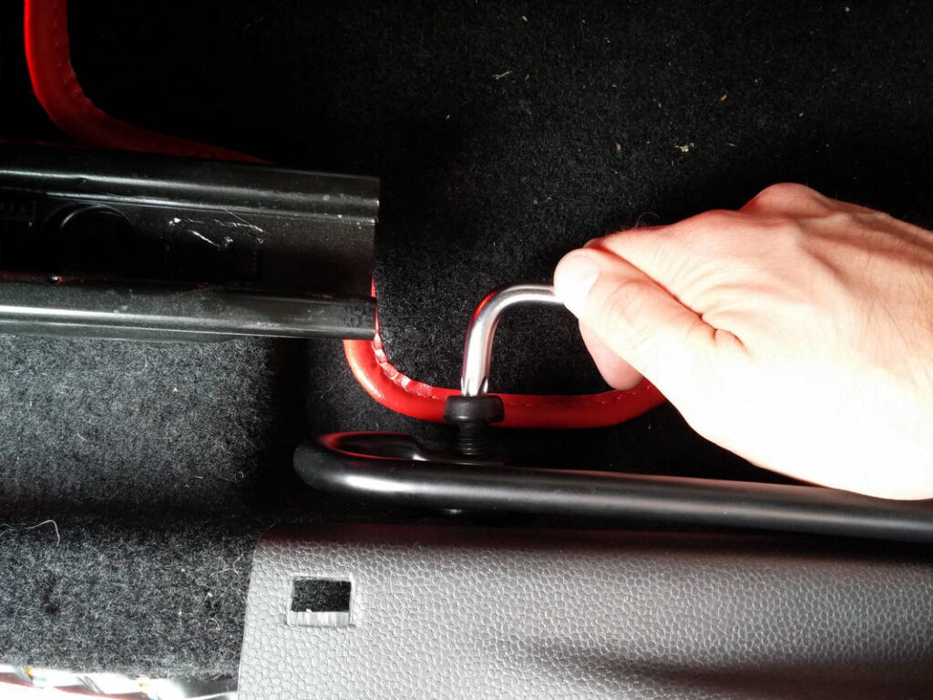
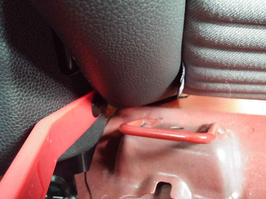
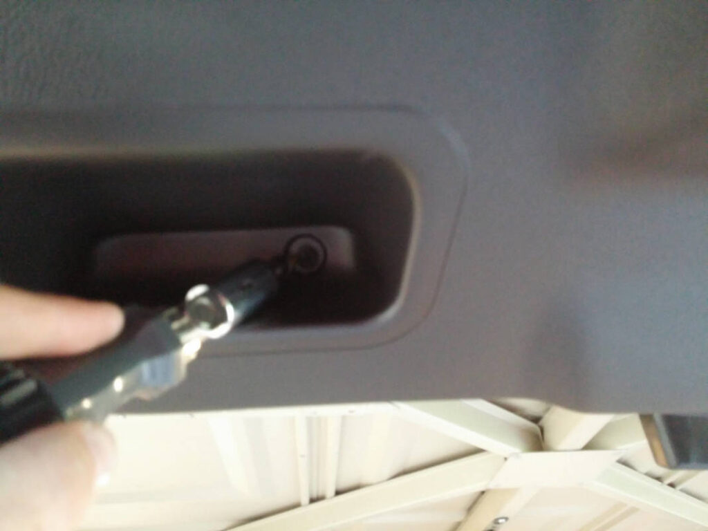
I removed a screw that was located above the rear quarter panel and then popped out the retaining clip that was on the top of the quarter panel (there is a small retaining clip by the seat belt that also holds the quarter panel in place- see further down). The parcel shelf trim was removed, and the carpet was then eased out from the rubber seal and removed from the boot.
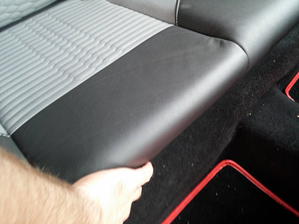
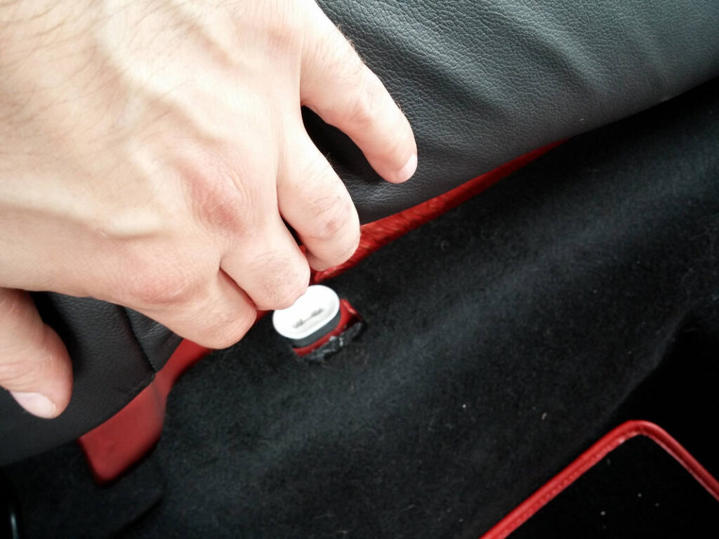
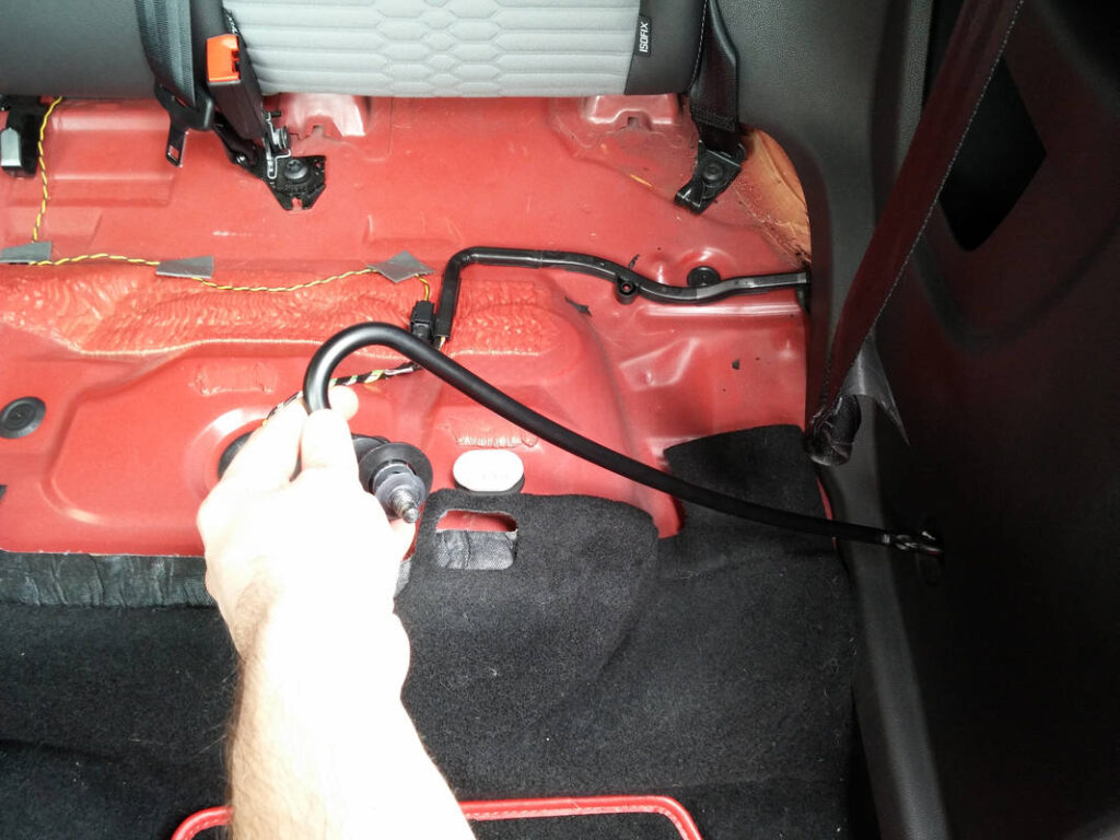
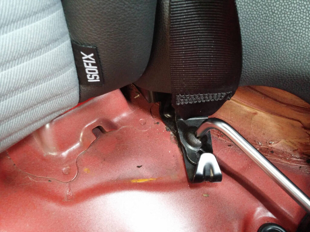
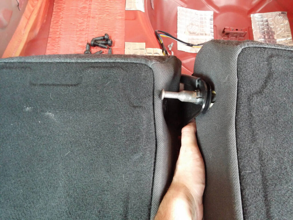
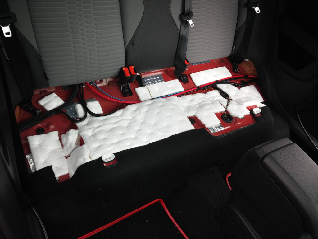
The removal of the rear seat was rather simple. There is a retaining clip on each side (socket is white in picture), and the seat was simply pulled to unclick each one. The rear of the seat is hooked to the seatbelt brackets and needs to be lifted off. You never know what you’ll find under there…
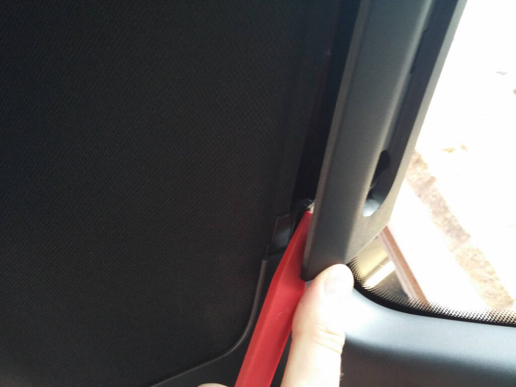
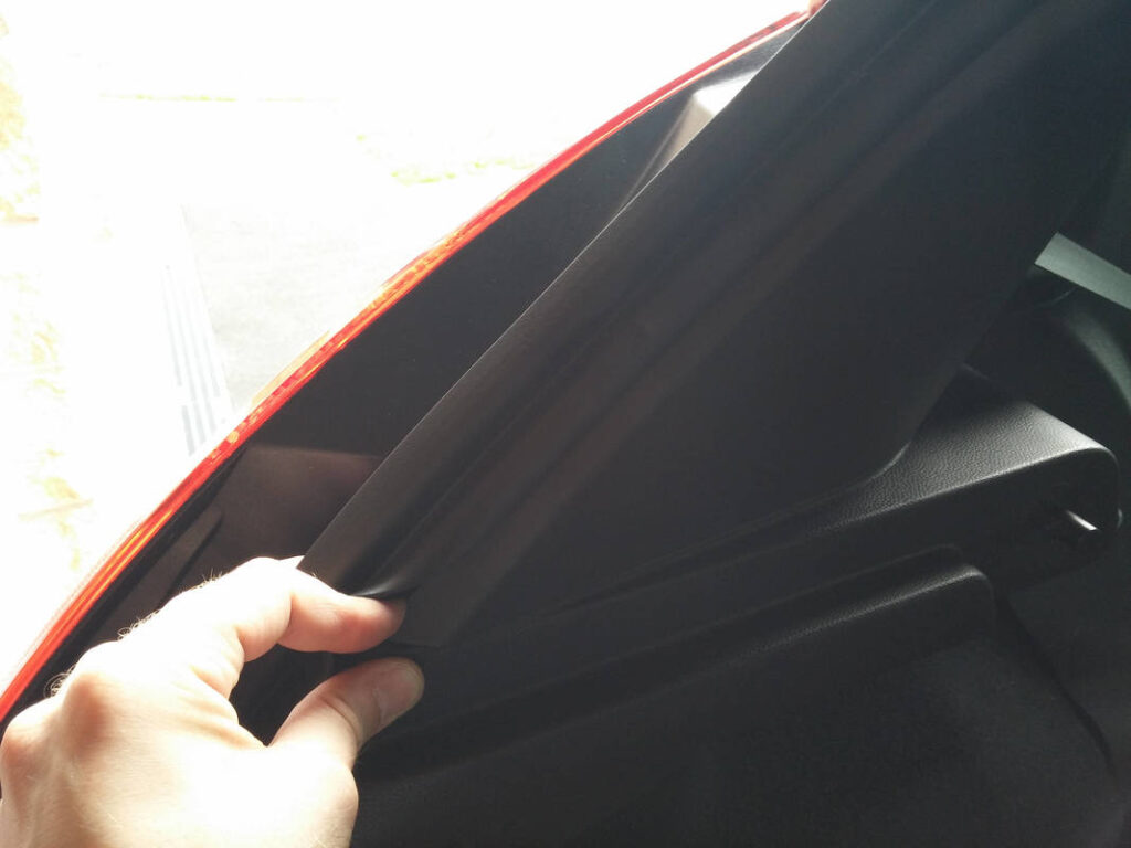
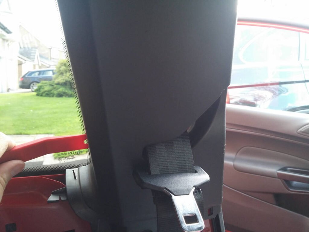
I began to remove the B pillar trim piece, but it looked like I had to remove the rear quarter panel before I could continue with this.
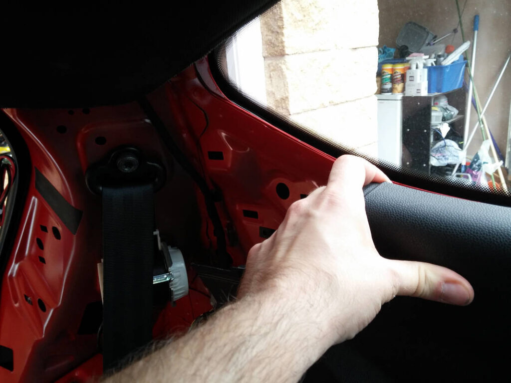
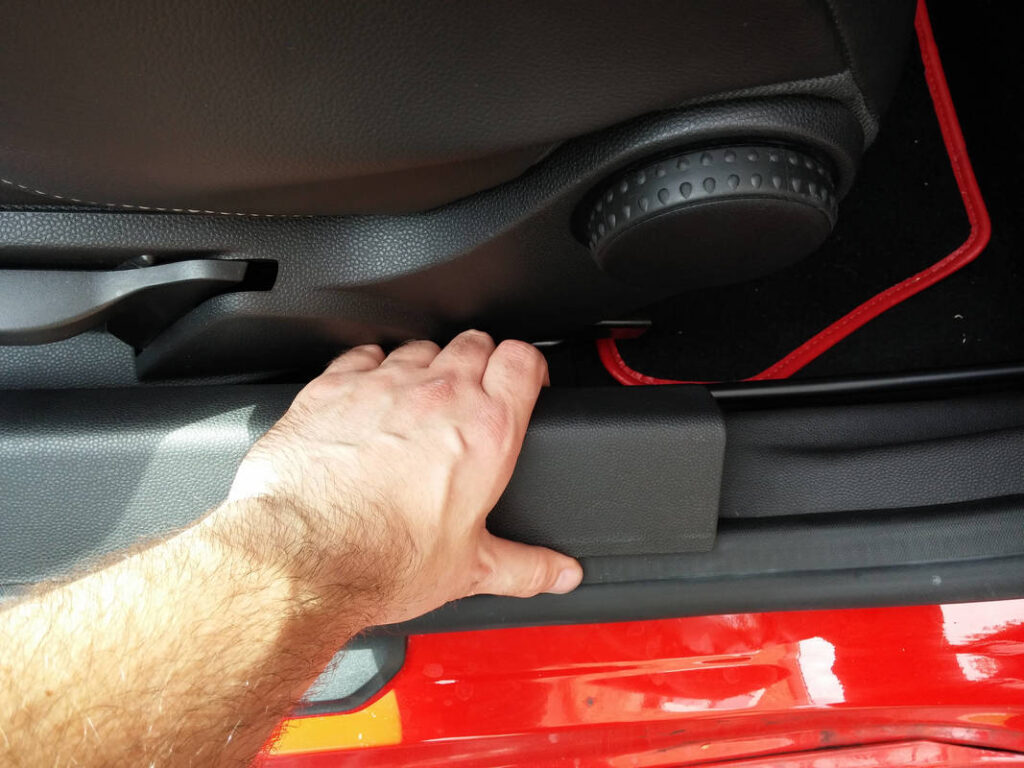
I worked around the rear quarter panel, unclipping all of the retaining clips at the top. I removed the kick panel to free the sill plate trim and removed that too.
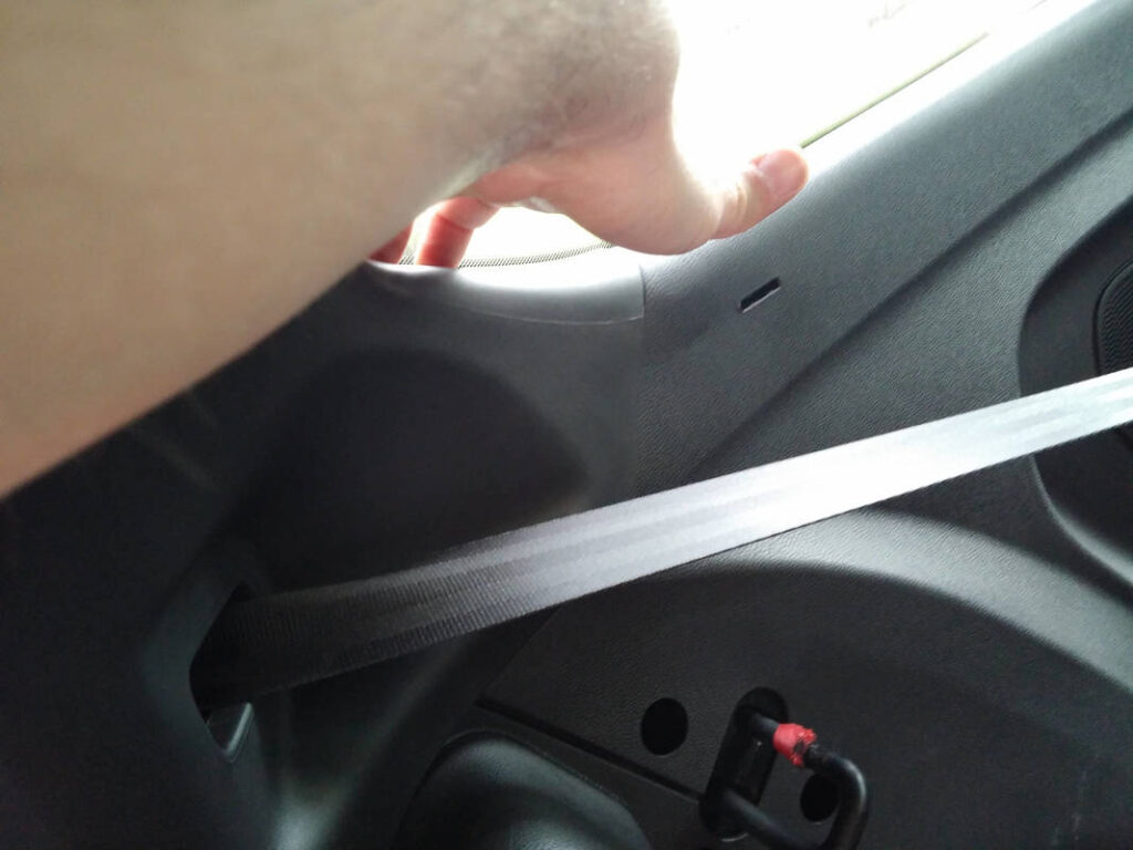
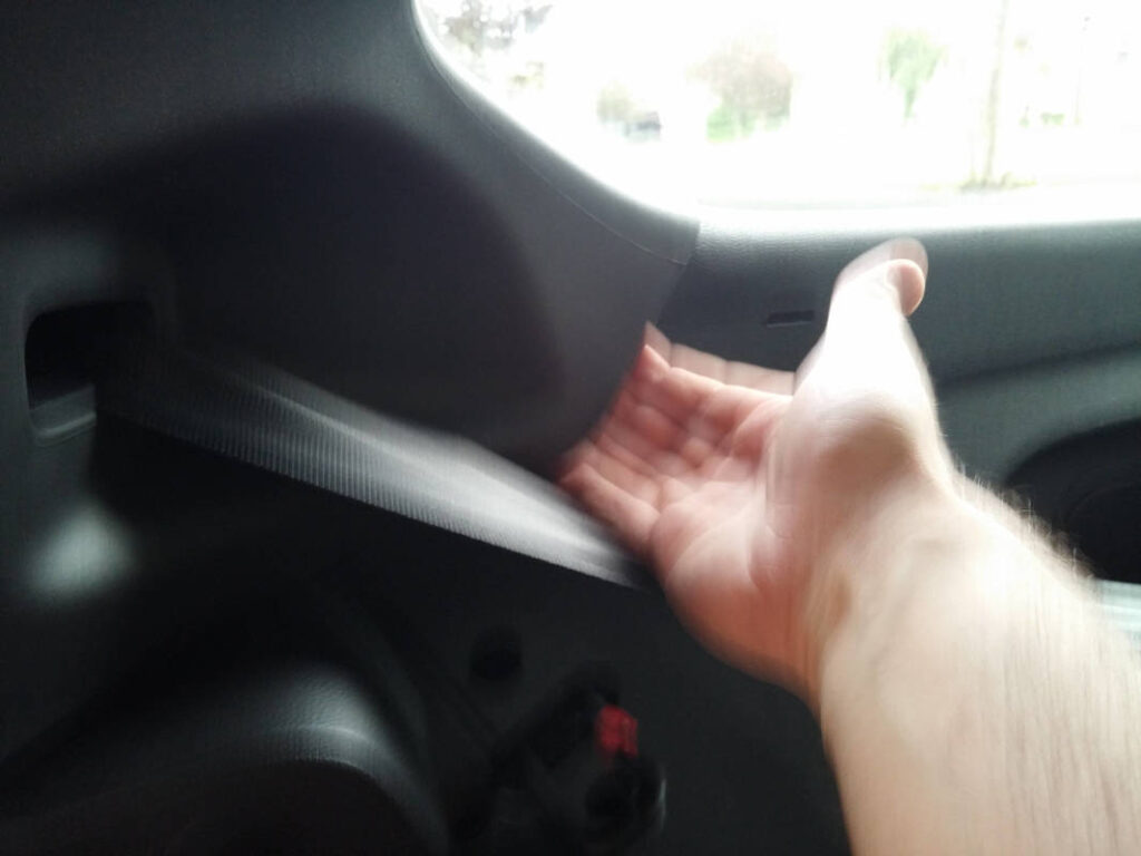
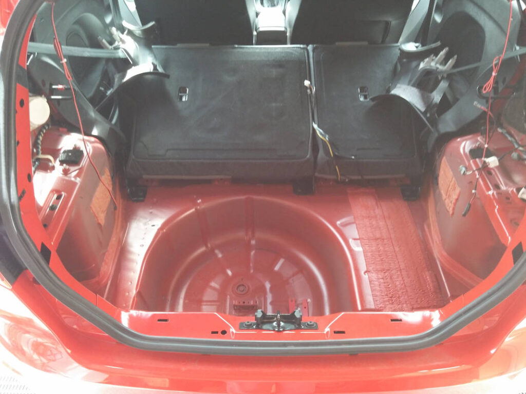
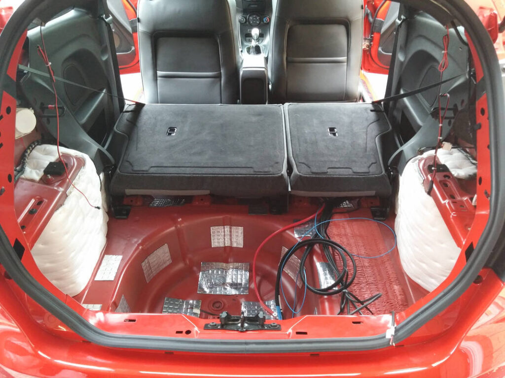
The front seatbelt rails are attached to the body through the rear quarter panel, so I had to remove those, and I also removed the rear seatbelts. With the rear seatbelts unscrewed I removed the upper boot panels that had been sliding on the rear seatbelts. The final retaining clip was removed; the seats and quarter panels were out!
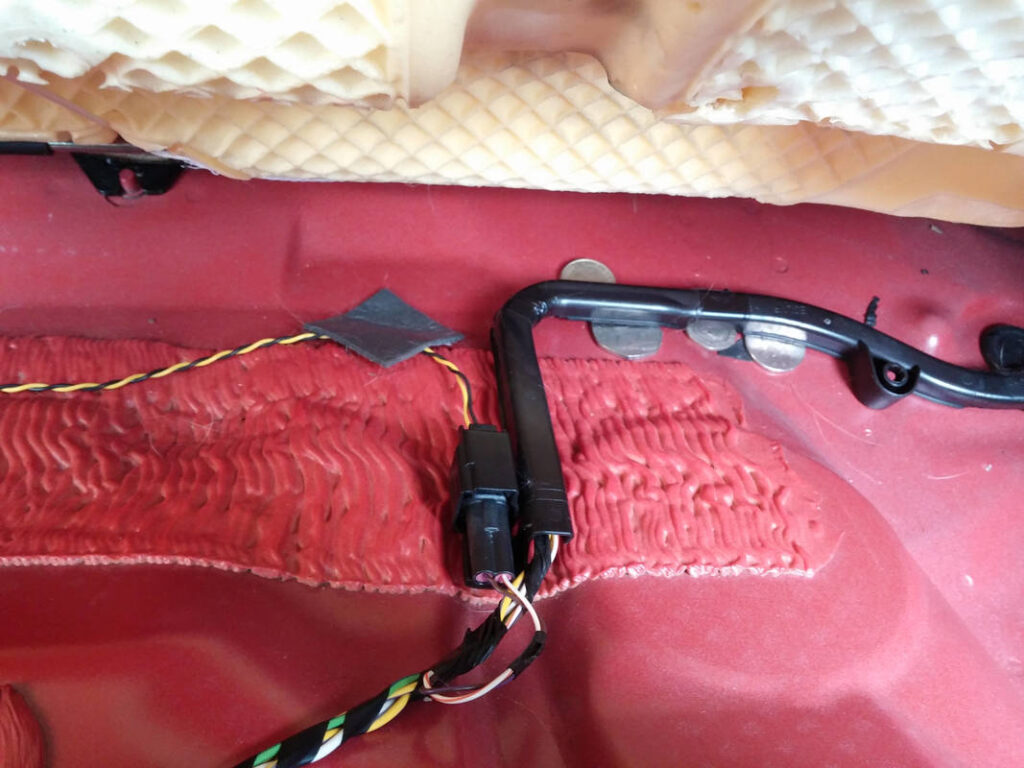
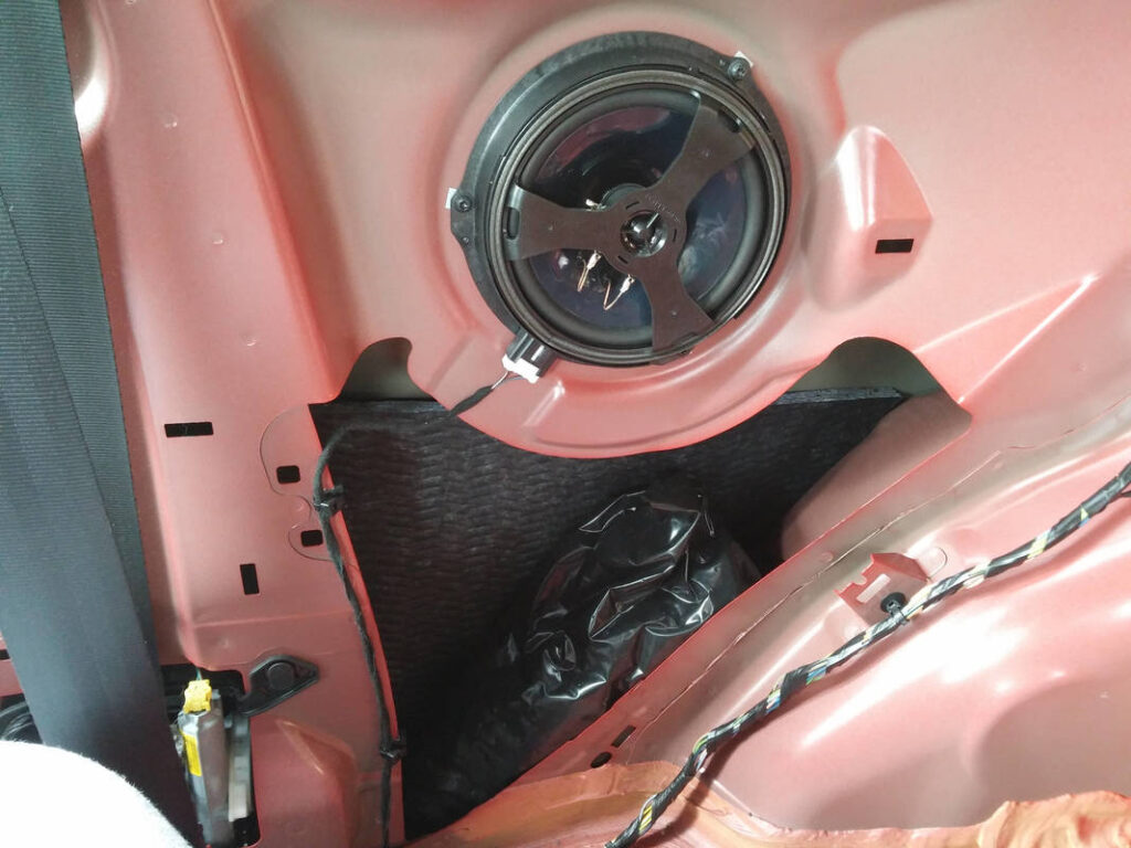
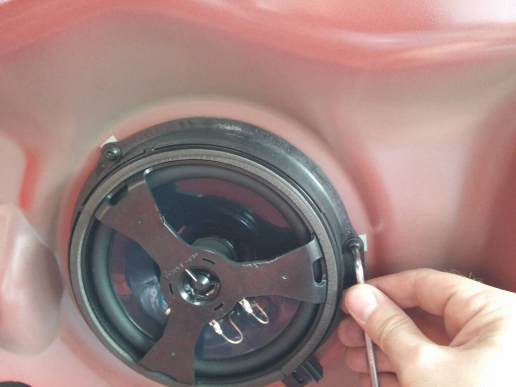
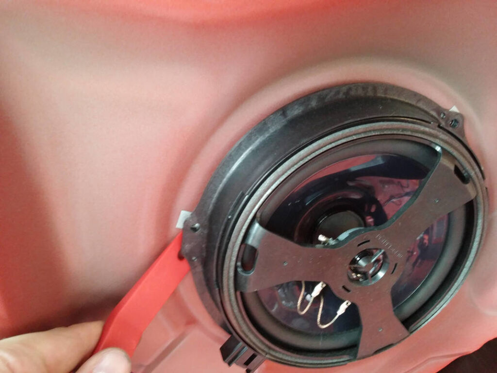
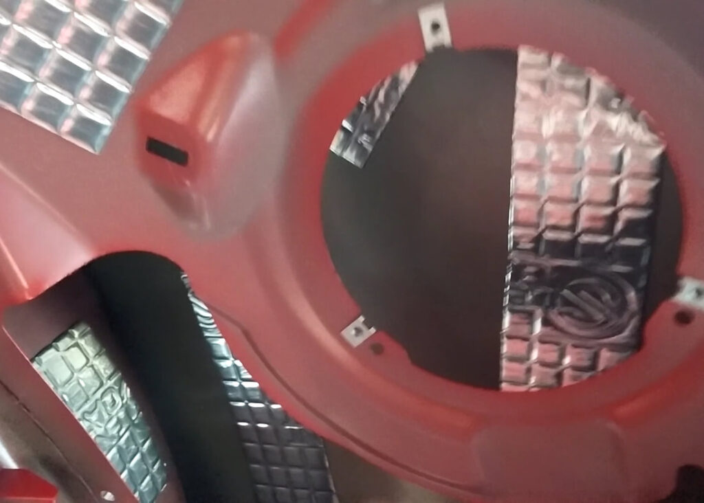
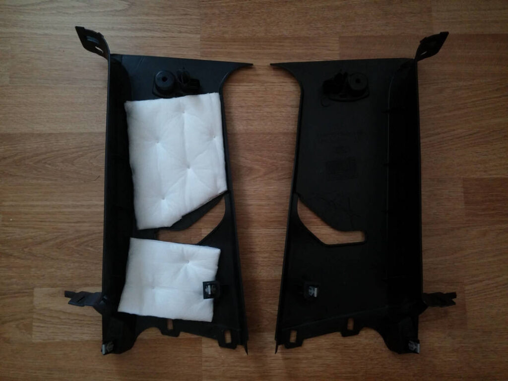
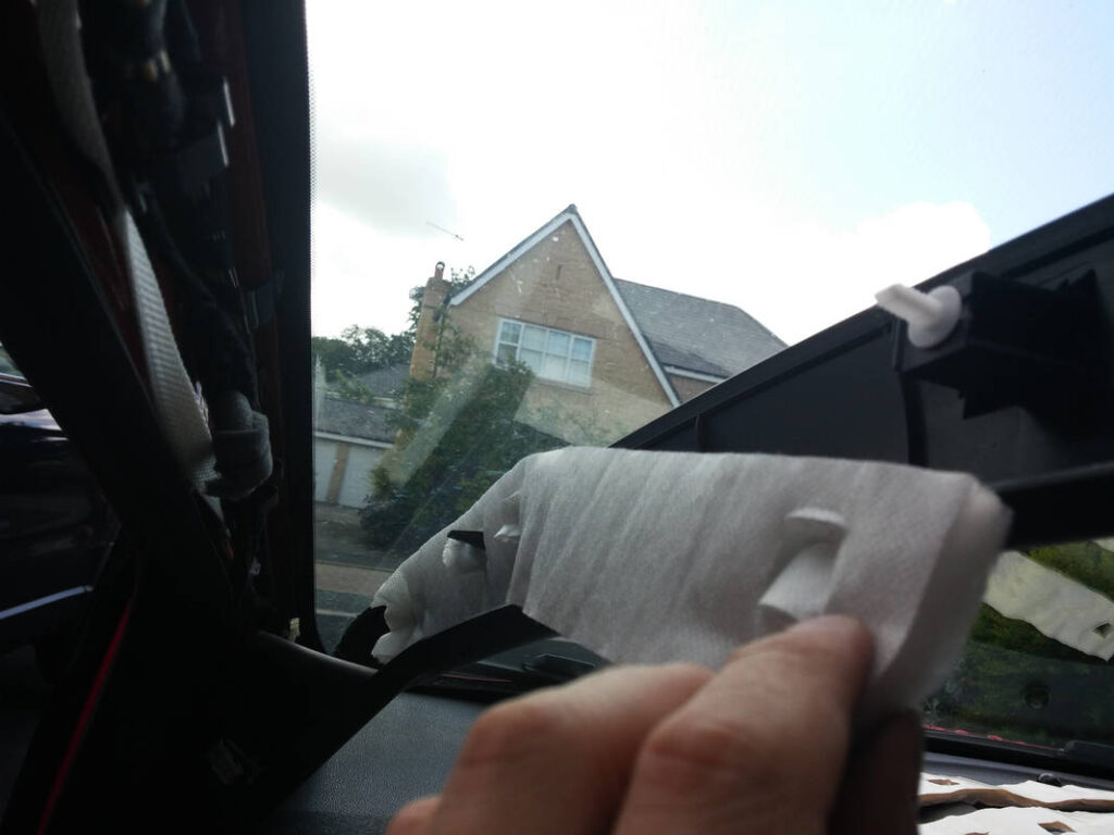
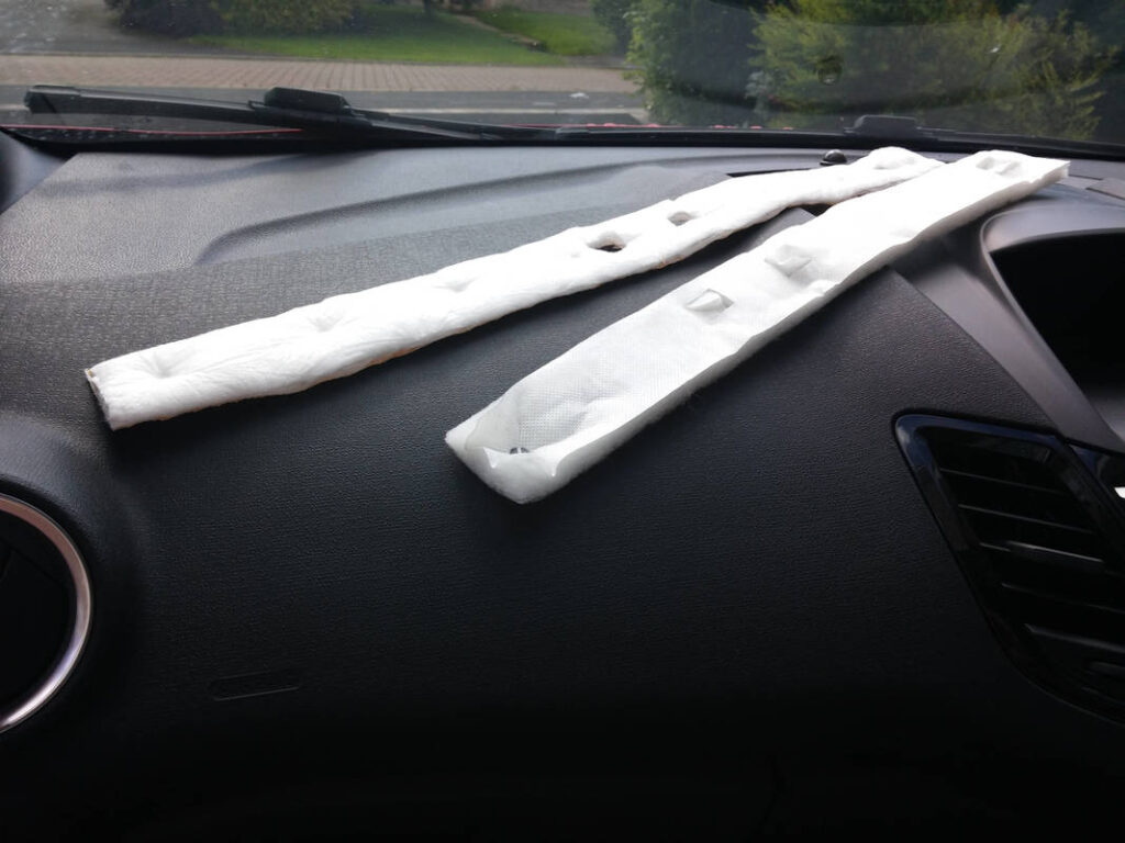
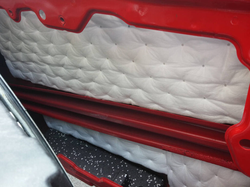
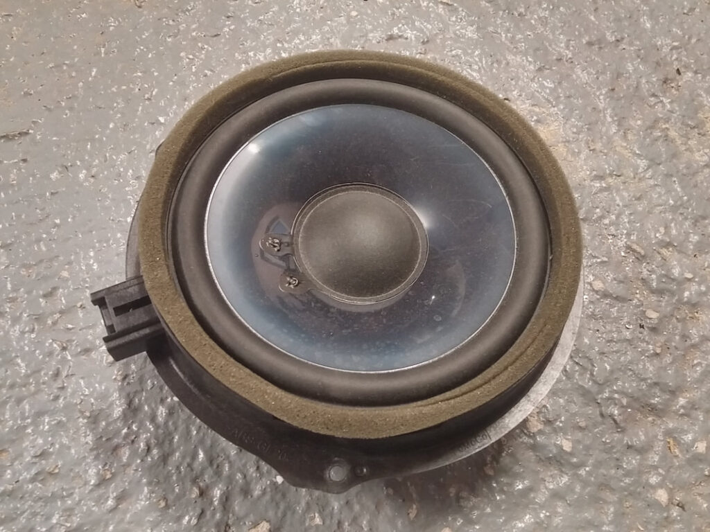
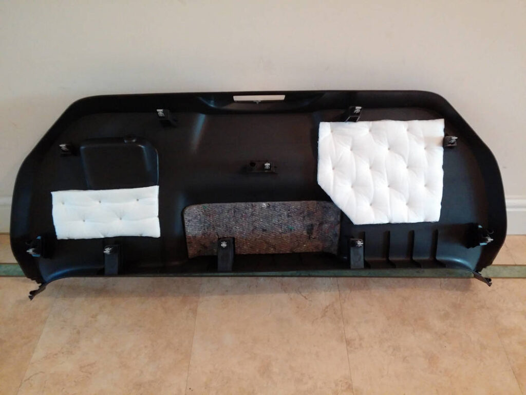
The OEM Sony coaxial speakers were then removed. It was interesting to see the use of felt sound insulation and a bag of wadding in the enclosure.
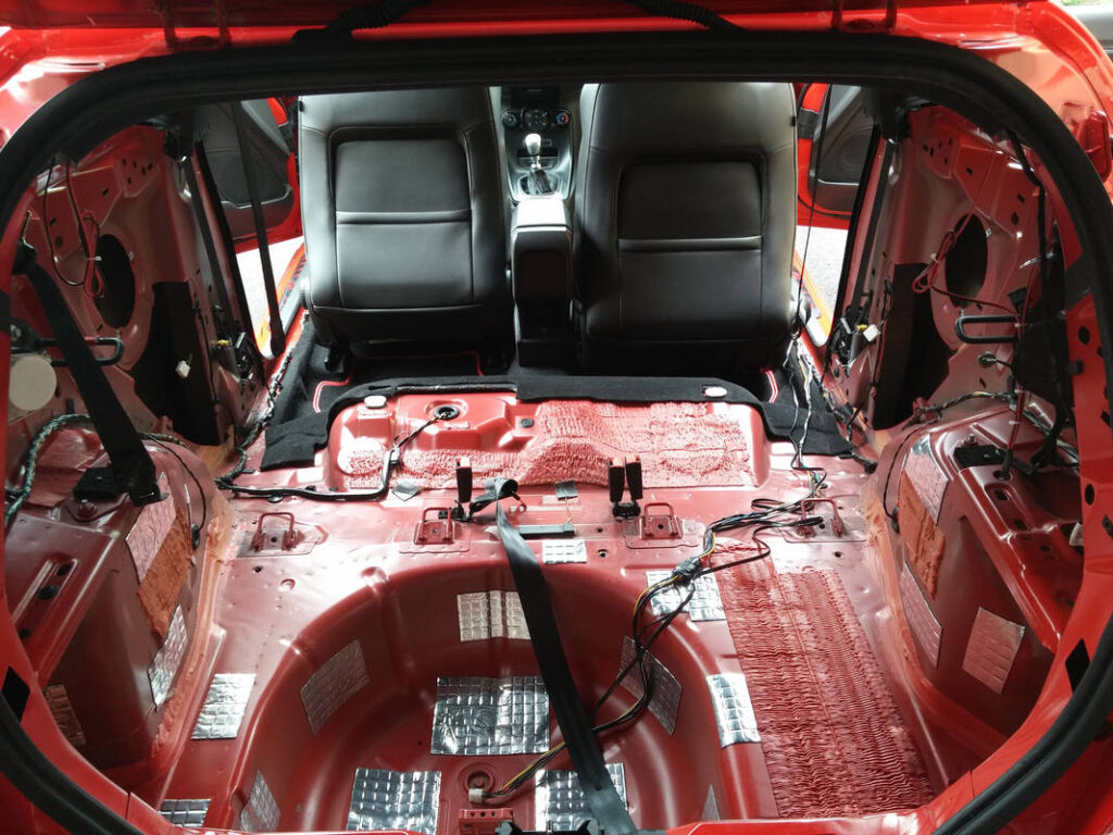
I followed the Pareto Principle regarding application of Silent Coat to my panels; I was unsure if this rule did apply to vibration damping, however chapter 4.1 of this book gave me a feeling that it would. I would hopefully get ~80% of the effects by ~20% coverage. The aim was to maximize the effects of the vibration damping whilst minimizing the added weight, thus preserving the driving characteristics of the ST.
Once stripped out, I gave my car a really good vacuum before wiping down the interior metalwork with IPA. Silent Coat has 10mm x 10mm squares stamped into the foil side of the sheet, which makes measuring and cutting panels of a particular size really easy. I found Silent Coat a pleasure to work with. It cuts easily with a stanley knife (I used a scrap of MDF as a cutting board) and is very sticky when the backing is peeled off. I bought a cheap roller and a cheap hairdryer to help ensure that the Silent Coat had good uniform adhesion to the panels.
I worked on a small section at a time. My method was not particularly scientific, rather based on feel and sound. I gave each panel a short sharp knock with my knuckle, and placed a different sized piece of Silent Coat down depending on how thin and hollow the sound was, until everywhere I knocked returned a dull ‘thud’. I used this technique throughout the car, including the roof, side doors and boot door.
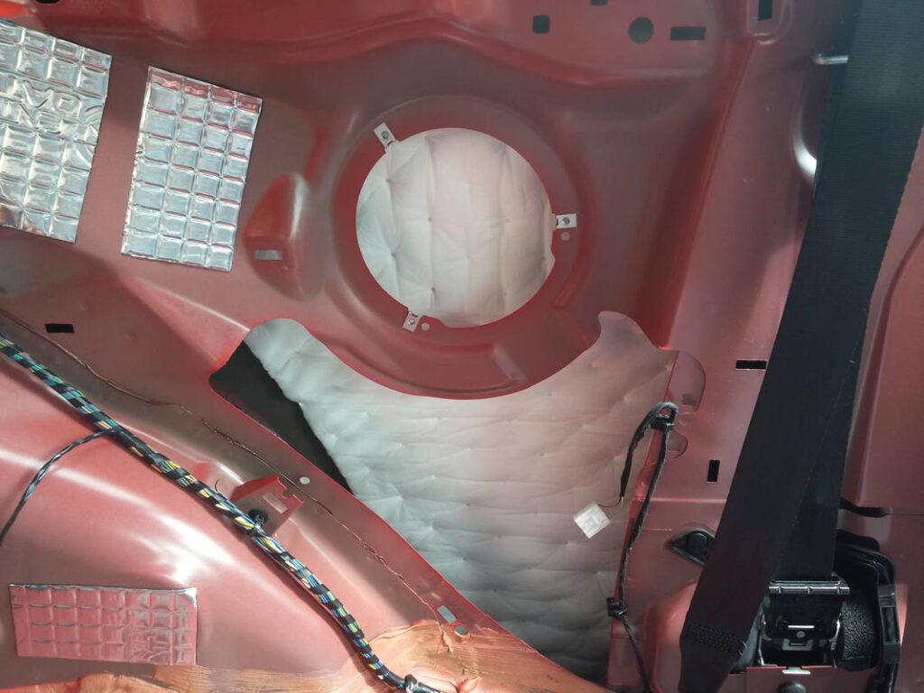
I found HydroWELD great to work with. It has dots where the material is welded together, spaced ~25mm apart, allowing for easy measuring. It cut with household scissors. I bought the self-adhesive variant, and it is really sticky. I measured roughly how big a piece I wanted, trimmed it to size, test fitted it and then, removing the backing a bit at a time, stuck it down. I applied pressure as I went, ensuring good adhesion and no air bubbles. This worked well for me. I covered (not 100% but remember Pareto…) all trim panels that had been removed, the roof lining, under the rear seat, the front doors, the rear wheel arches and the rear quarter panels (replacing the OEM felt sound insulation but keeping the OEM bag of wadding).
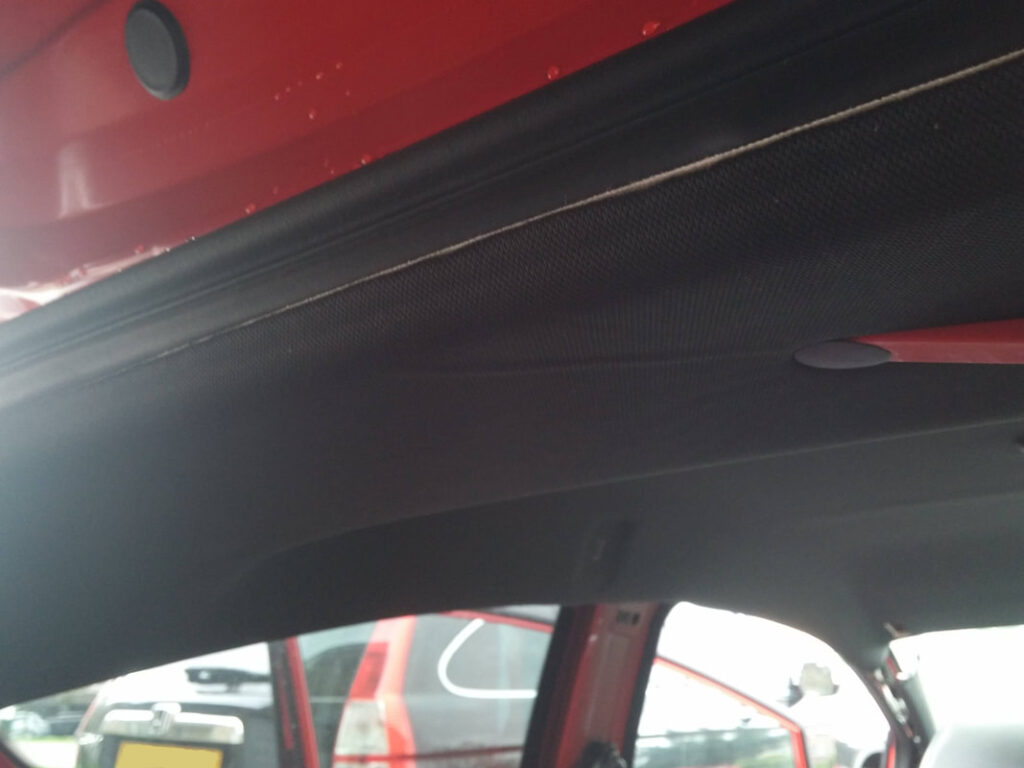
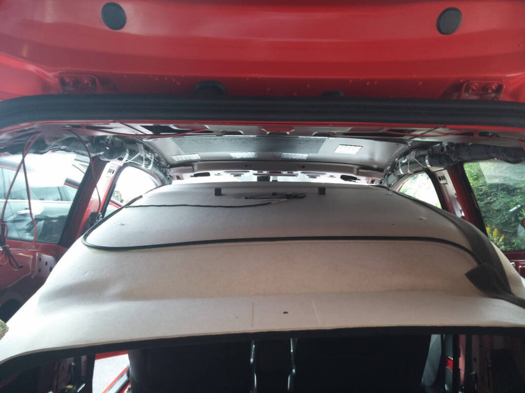
The roof liner cannot actually be removed from the car without removal of the front windscreen, so when I say ‘removal’, I use that term loosely…
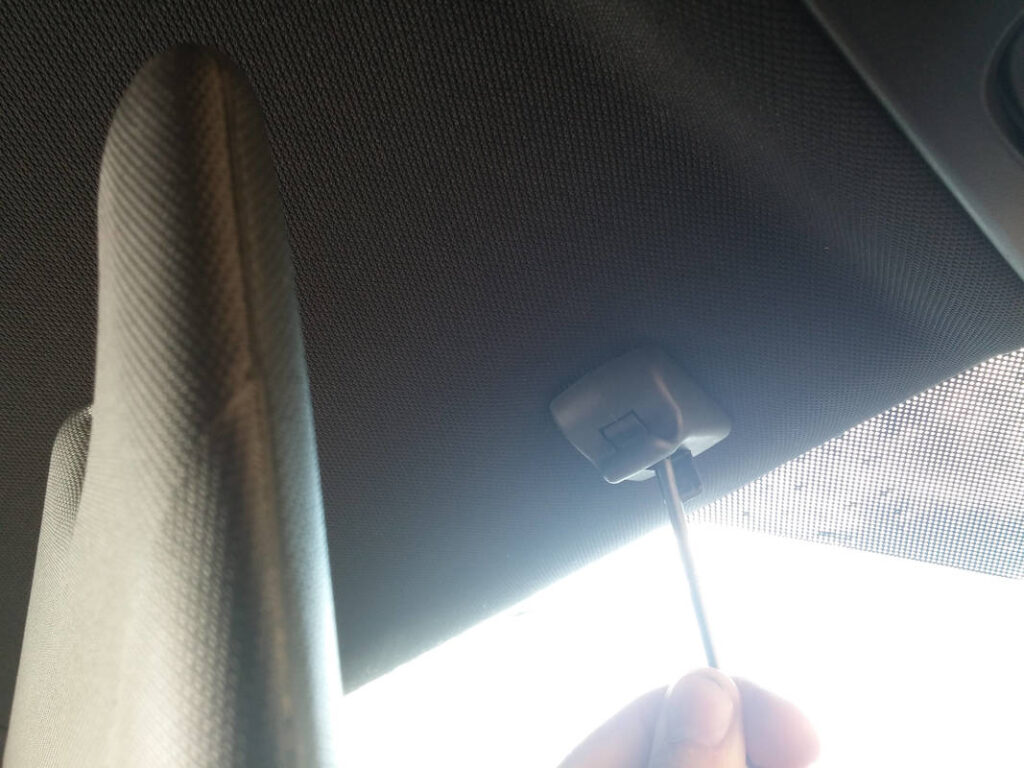
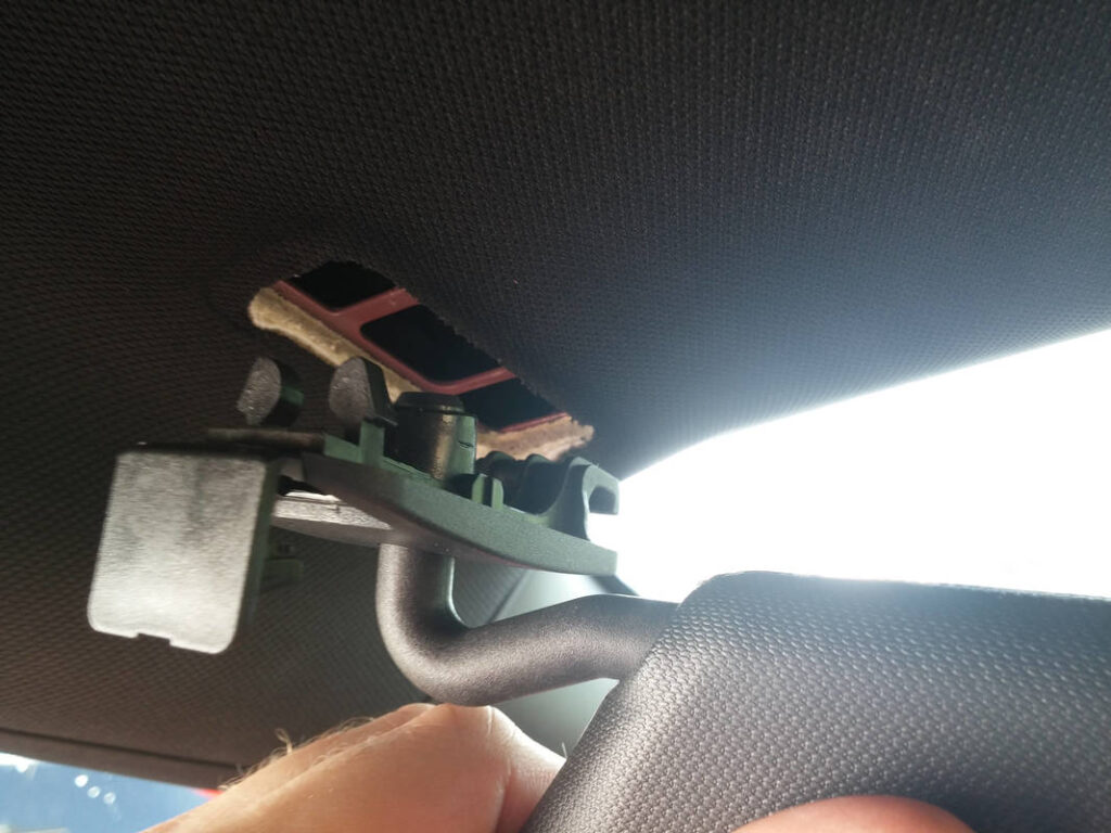
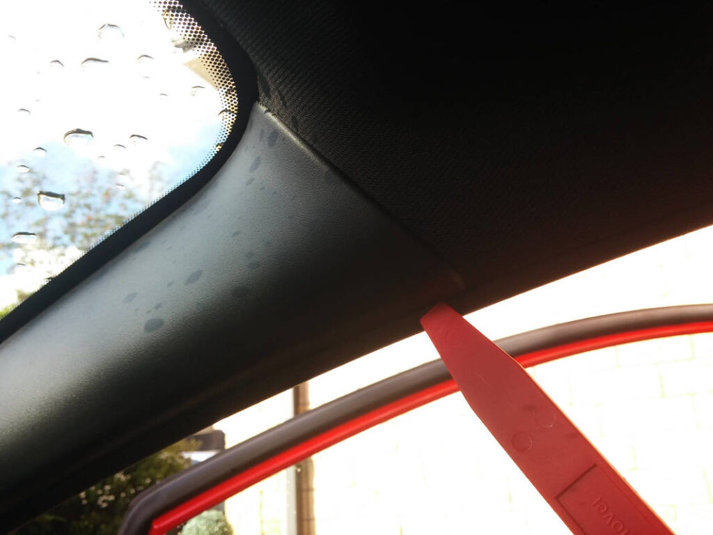
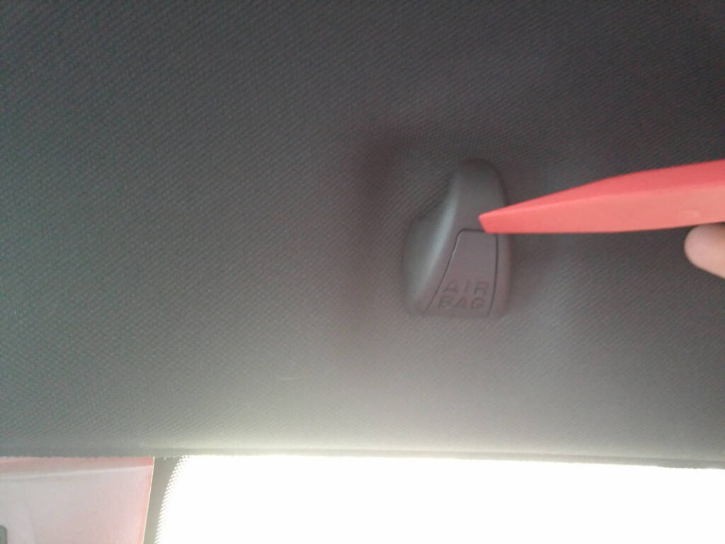
I first removed the sun visors and retaining clips. the visors levered out towards the doors. I worked the A pillar trims loose but they did not want to separate from the dash so I just left them, and then finished removing the B pillar trims.
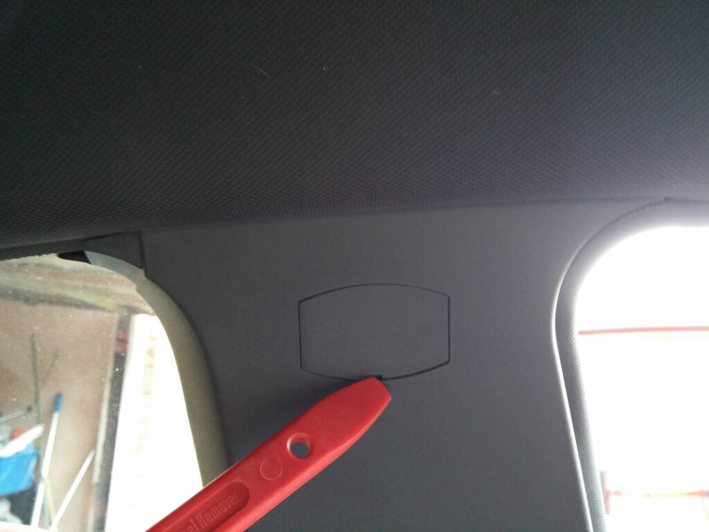
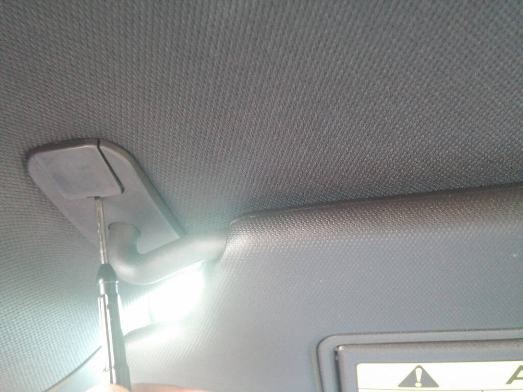
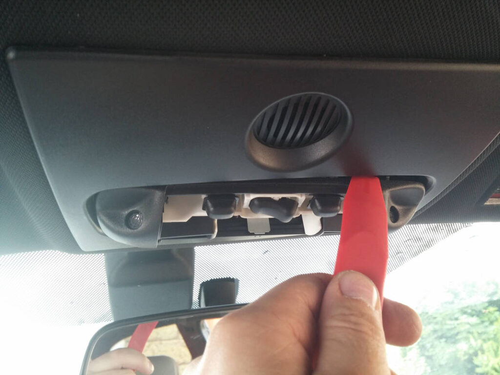
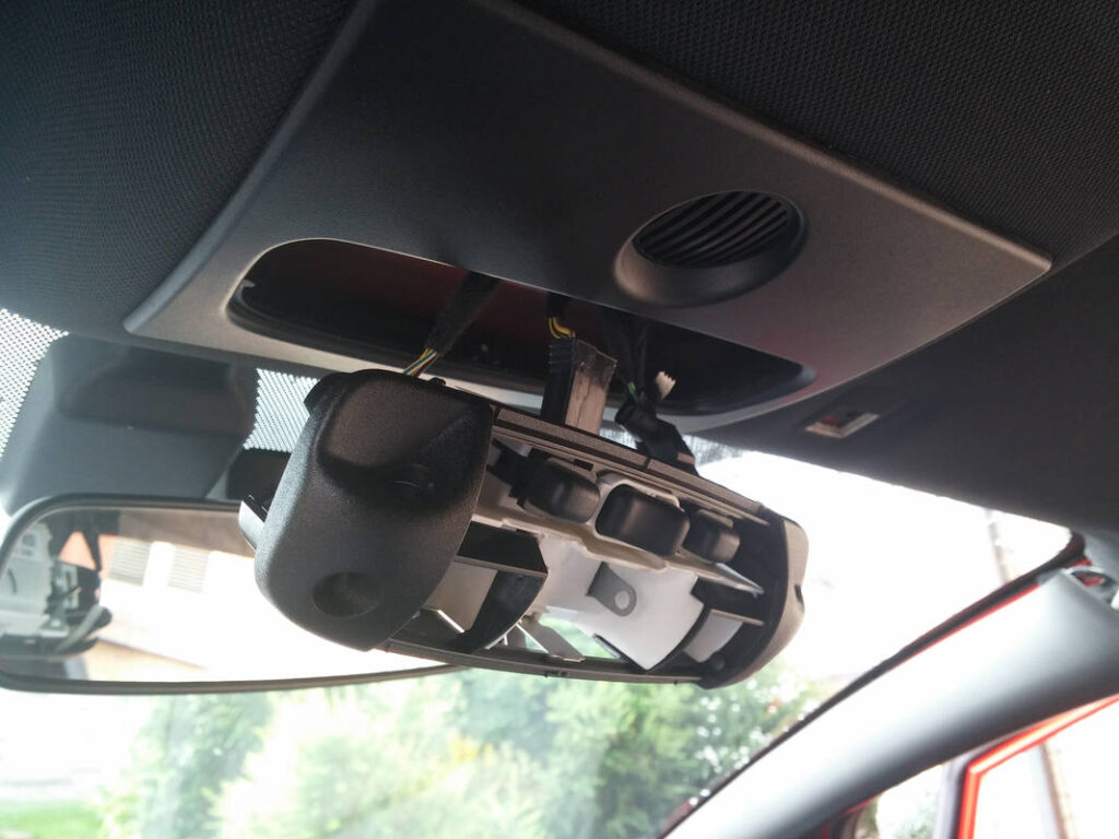
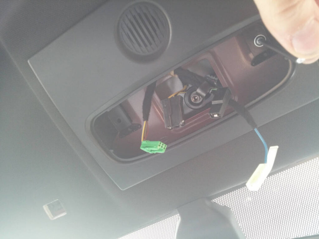
I removed the coat hooks by pulling out the tab (I had to pull hard- I was worried I was going to break it). The Dome light came out next, with the removal of a couple of screws freeing the dome light surround from the roof.
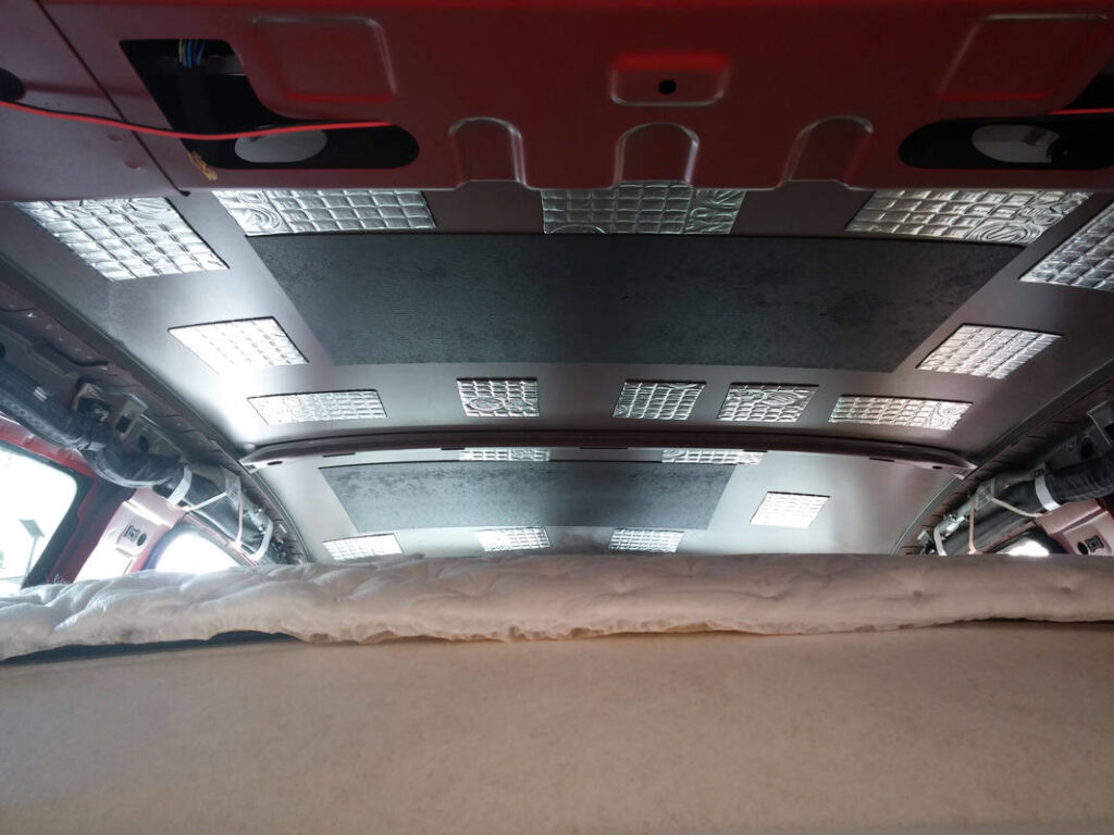
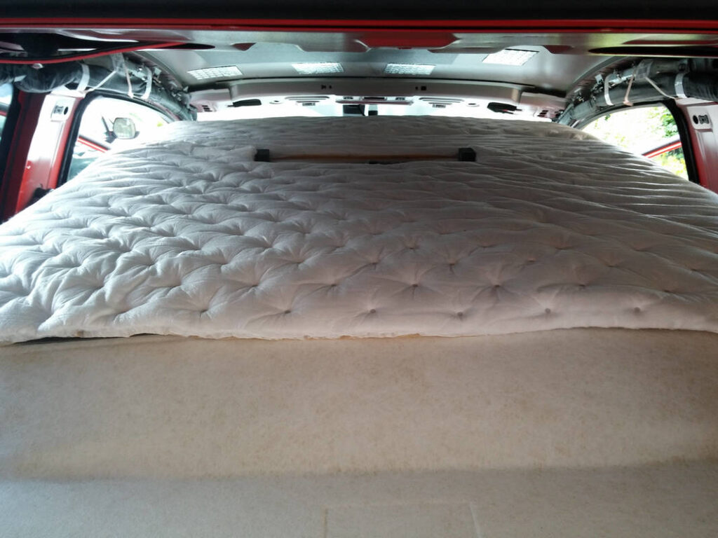
Two retaining clips were removed from the rear of the roof lining and it was free. The A pillar and roof lining were lined with HydroWELD, and Silent Coat was applied to the roof.
This tutorial was for a different Fiesta door trim but was of great help to me.
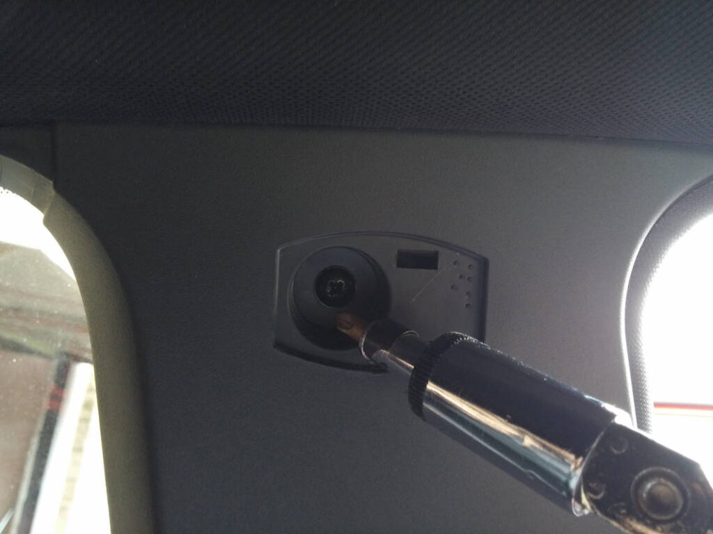
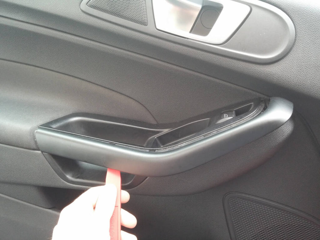
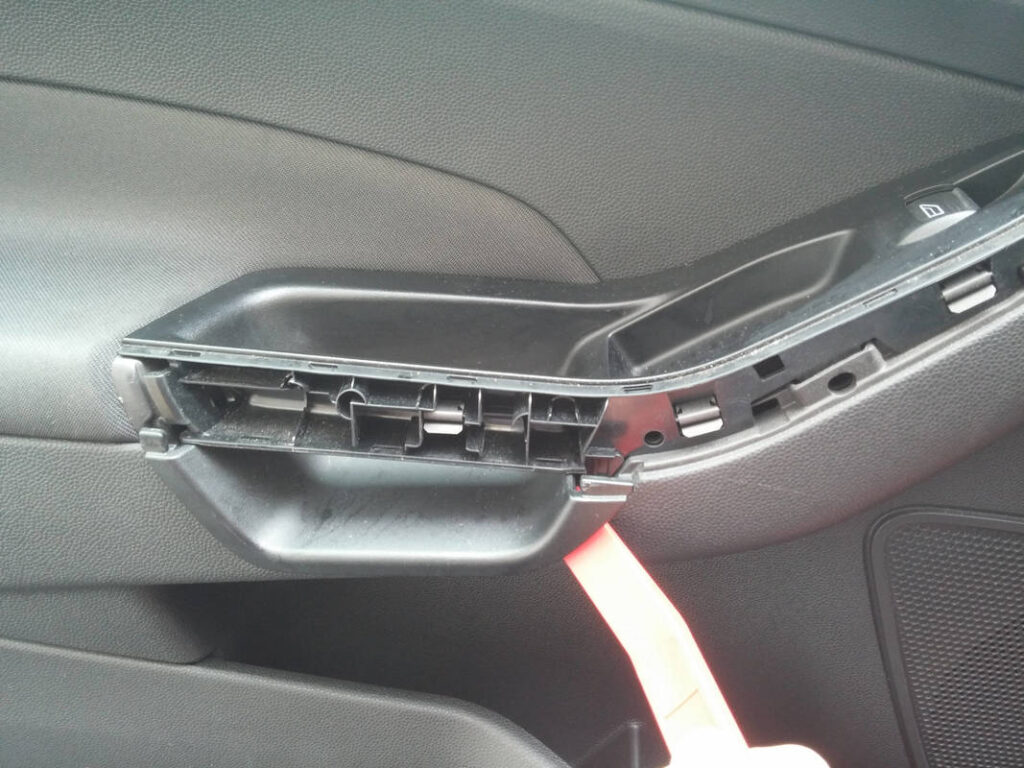
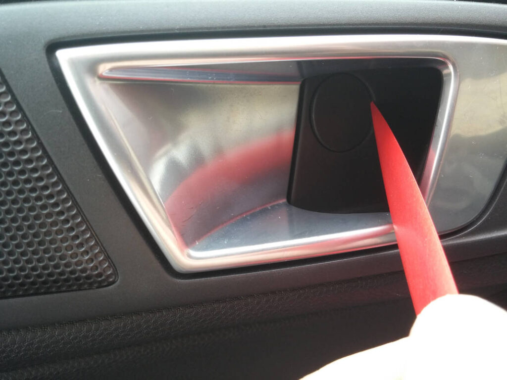
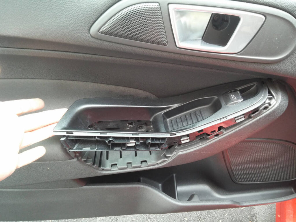
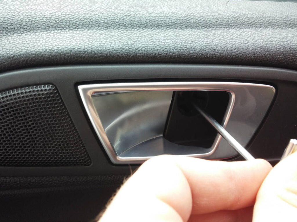
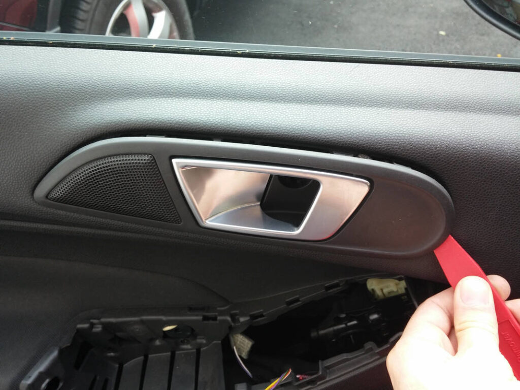
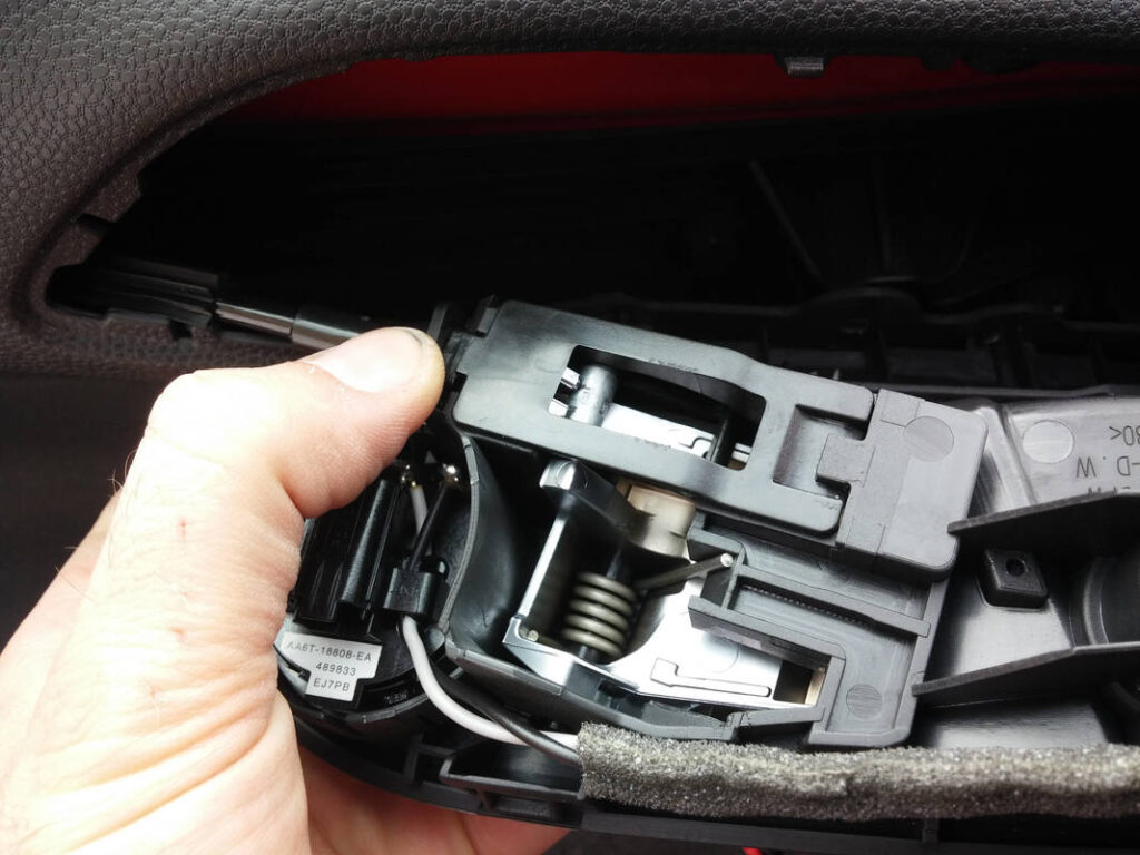
I pried off the outer handle trim cover, followed by the lower handle cover. I poked out the screw cover. I then removed the handle assembly.
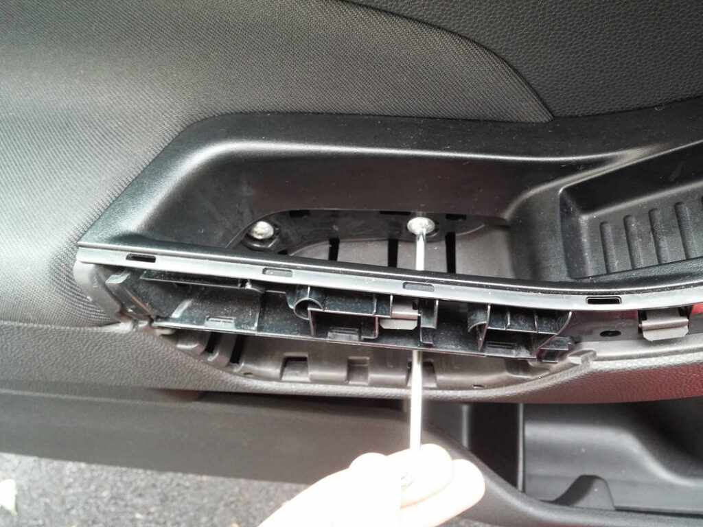
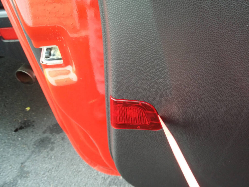
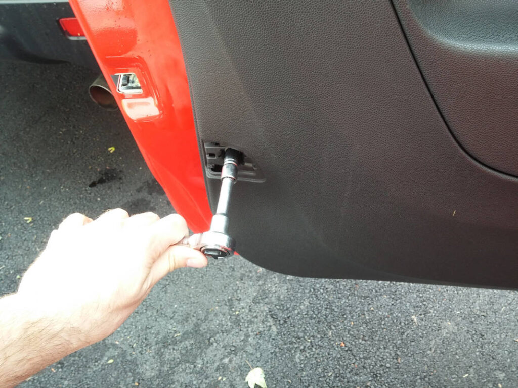
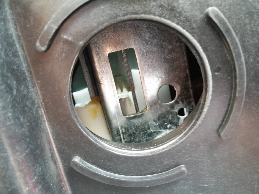
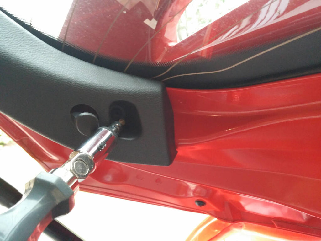
I removed the screw from behind the door handle. I then popped off the reflector to expose a bolt and removed that. The door handle pried of easily, I just had to unhook the cable.
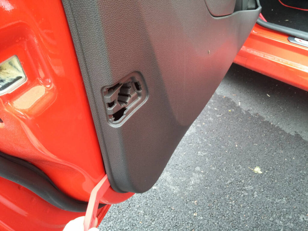
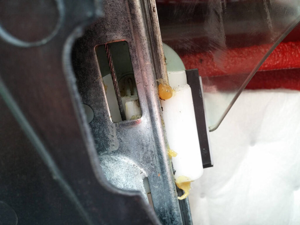
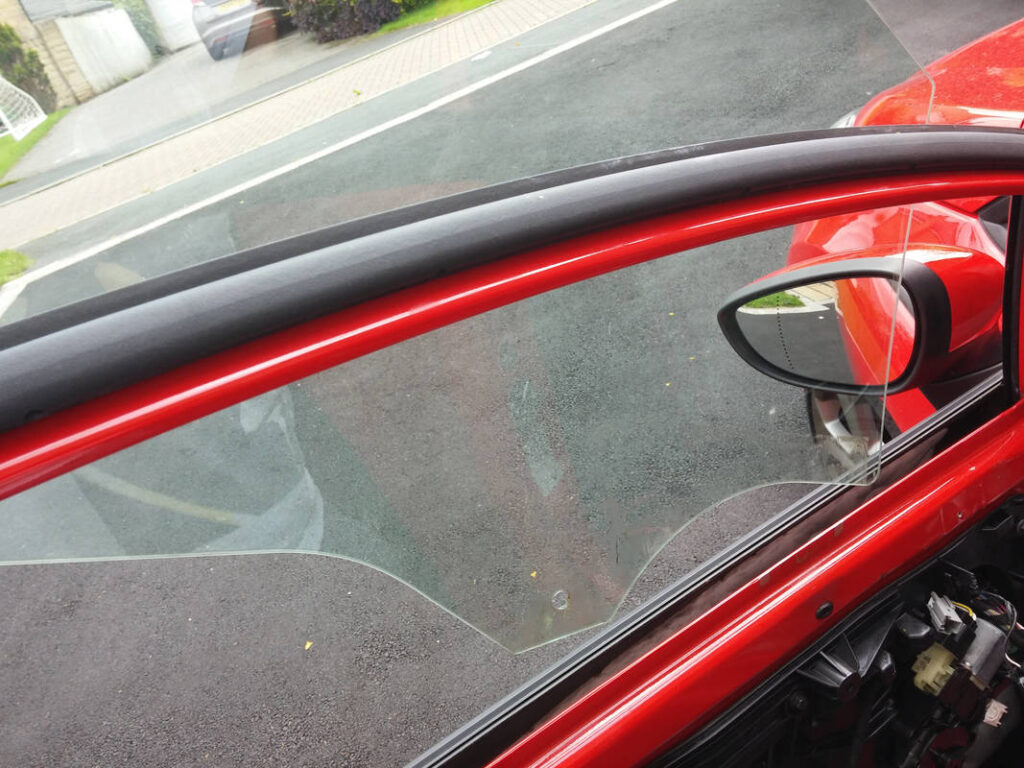
I worked round the door trim with the pry tool and then disconnected the electrical connector for the ambient lighting before the panel could be removed completely. I then removed the windows by winding them down to line the retaining clips up with the holes, unclipping them and carefully lifting them out.
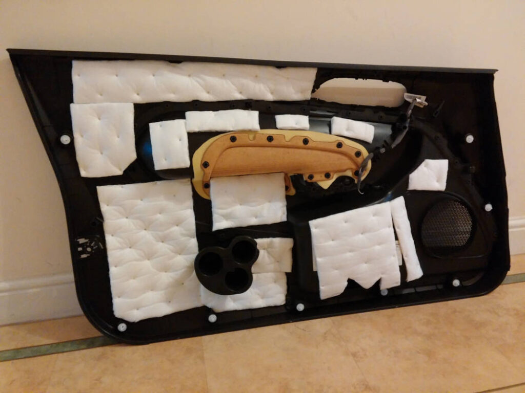
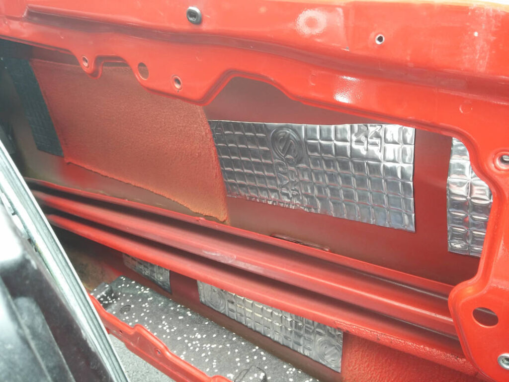
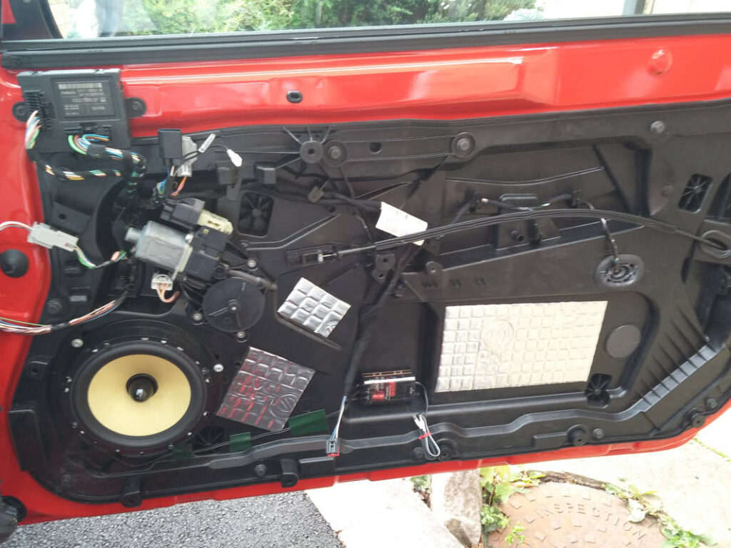
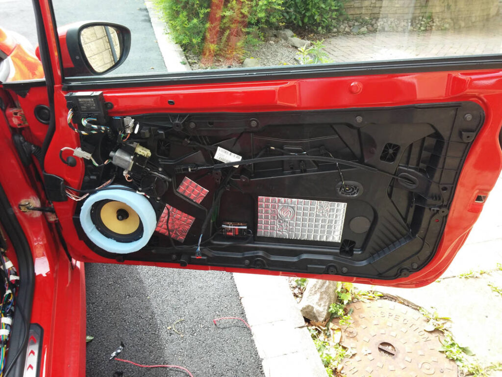
The insides of the door skins were cleaned and then given a wipe down with IPA. Silent Coat was applied to the door skins using the technique described earlier, and then it was insulated with HydroWELD. The door liner was then reinstalled before refitting the window. This was confusing at first- it doesn’t look like it should fit but it obviously does… Tilt the glass forward at an angle being careful not to scratch it; it’ll slide right back in and click into place.
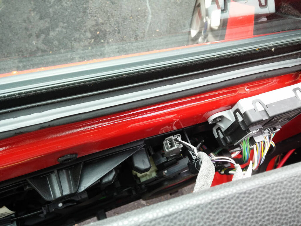
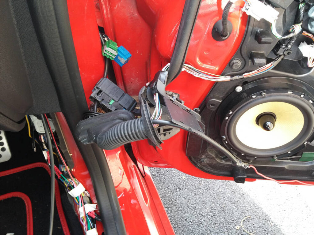
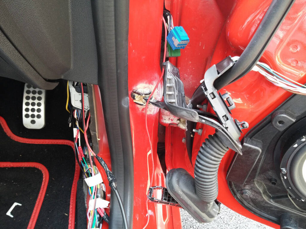
I fitted the new speakers and used automotive double sided tape to secure the crossovers. I added some Silent Coat to the thinner parts of the door liners to add mass. An unexpected hurdle I overcame was routing the speaker cables into the doors. I don’t know why I expected to see cable bundles passing into the doors- having connectors here allows for quick and easy replacement of a standard door. What a lovely connector design; the blue and green male connectors mate with the black 3-way female connector, a rubber boot providing protection from the elements. As luck would have it, the bottom section was unpopulated, so I hollowed it out, fished my speaker cable through and connected it to the crossover. Ooh, that was a close one…
My DIY foam speaker rings fit nicely in the space- any thicker and I might have run into issues. Another interesting point worth noting is that the OEM Sony component woofers in the doors have foam rings (the rear coaxials have foam gaskets). The engineers at Ford and Sony will only have put them there if they performed a function, so they must do something quantifiable to the sound…
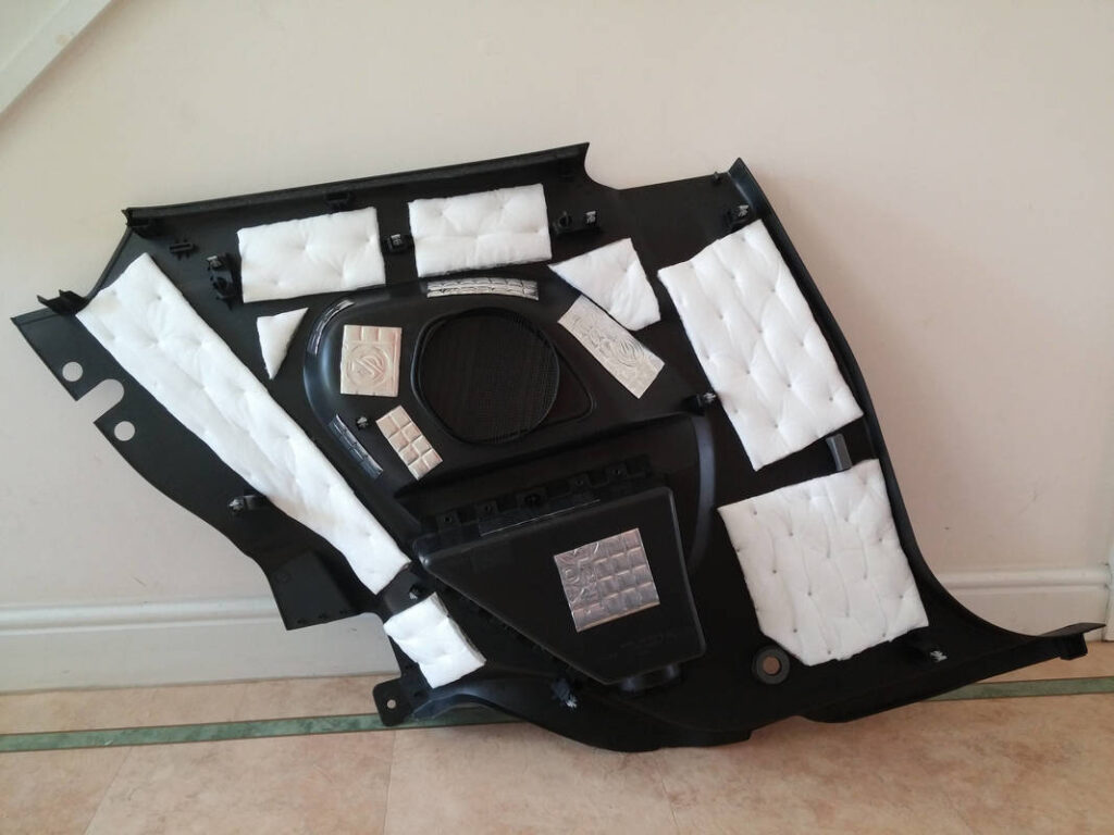
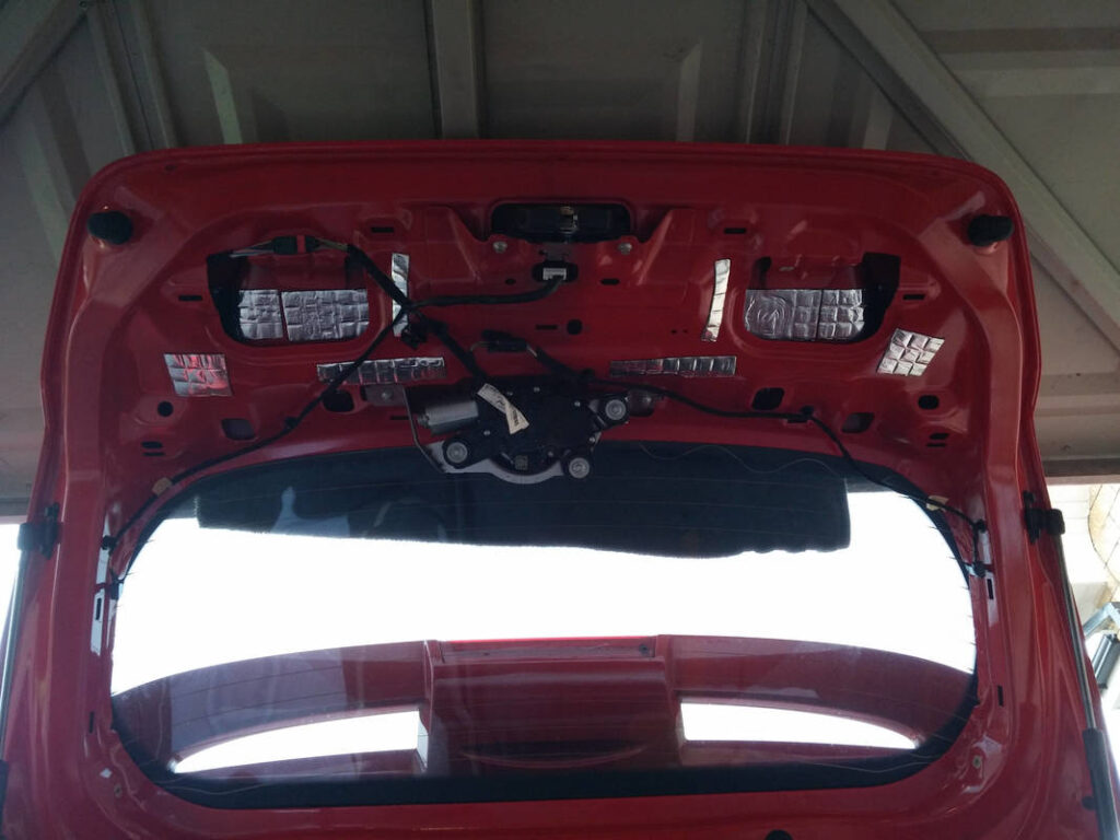
This was relatively straighforward. Three screws securing the trim were removed, and then the trim was pried off, unclipping the ten retaining clips one by one. Silent Coat was applied, including into the gaps where I could reach. I applied HydroWELD to the areas of the trim that would allow for it- the panel wouldn’t fit otherwise.
WARNING: CAR AUDIO CAN DRAW HIGH CURRENT- INCORRECT WIRING AND FUSING MAY RESULT IN FIRE! IF IN DOUBT CALL IN A PROFESSIONAL!
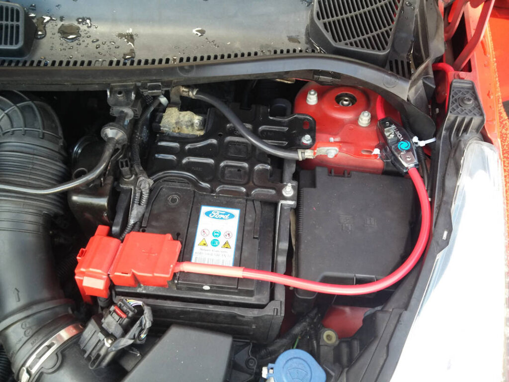
The supply cable to the boot must be fused BEFORE it gets to the boot. The reason for this is simple: All of the cable prior to the fuse is unprotected. In the event of a short on an unprotected wire, current will only be limited by the battery’s ability to supply it, potentially melting the cable and starting a fire or causing the battery to explode. This video is a good demonstration of the potential danger of shorting a car battery.
Kenwood recommend in the X801-5 manual to: “To prevent fire caused by a short in the wiring, connect a fusible link or breaker nearby the battery’s positive terminal”. Alpine have a similar recommendation in the MRV-M500 manual, stating: “Be sure to add an in-line fuse with the battery lead as close as possible to the battery’s positive (+) terminal. This fuse will protect your vehicle’s electrical system in case of a short circuit”.
I decided to run 25mm^2 (4 AWG) power cable to future-proof the system. I needed nowhere near the power handling ability of 4 AWG cable (135A x 14.4V = 1944W), for this build, but if I decided to upgrade the install later, or (heaven forfend) sell the car, the new owner could upgrade it easily if they wanted to.
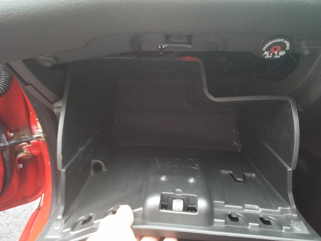
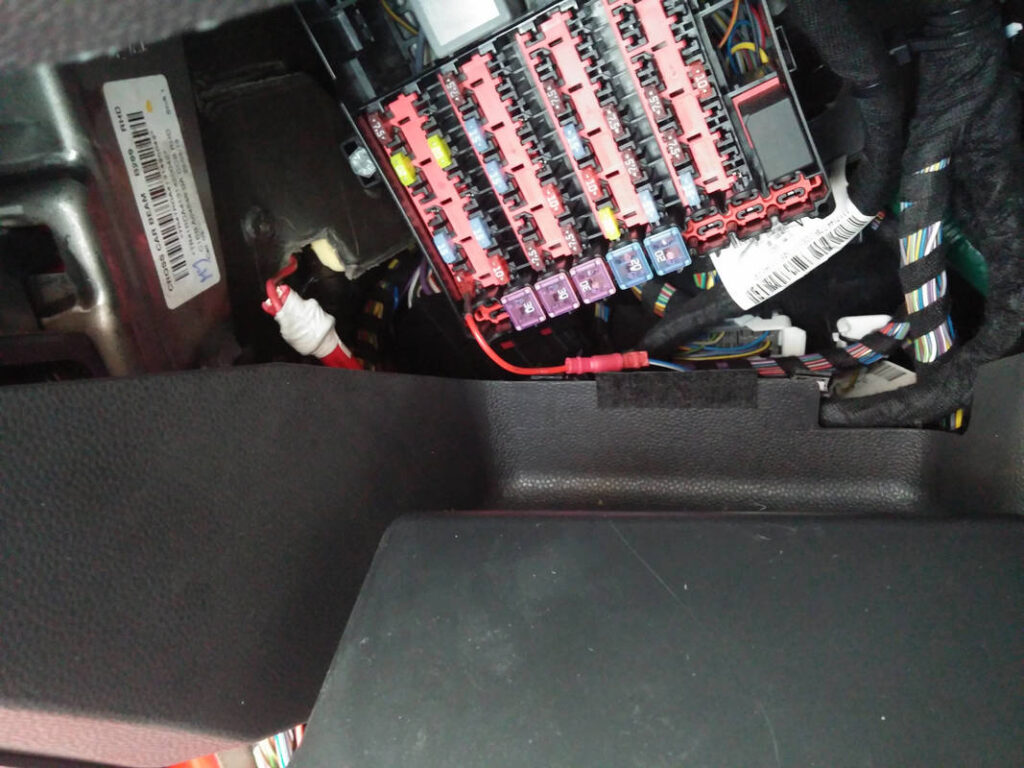
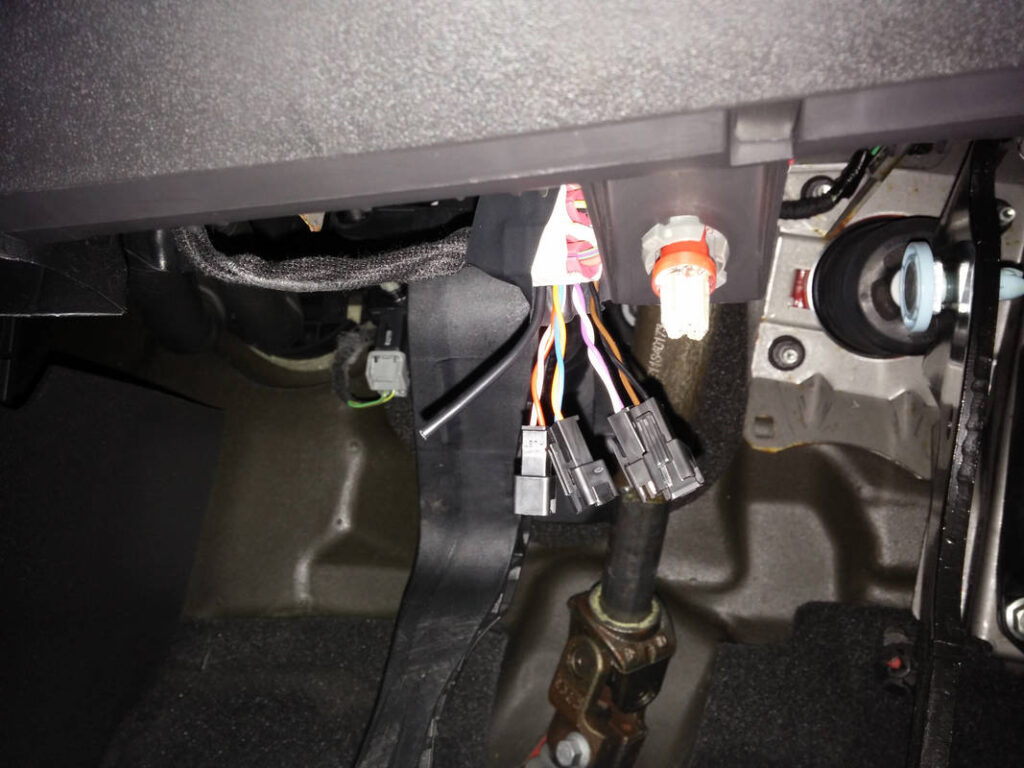
The battery side of the 25mm^2 (4 AWG) tri-rated cable was first cut to length, prepared and screwed into the mini ANL fuse holder. The glovebox was opened by squeezing the sides to expose the interior fusebox. The power cable was attached to a piece of ~16 AWG wire which was passed up the side of the dash and out of the hole where the blanking plug went. Fishing the cable through wasn’t easy; it’s not very flexible and I was worried that it wasn’t going to fit but…patience and perseverance was all that was required.
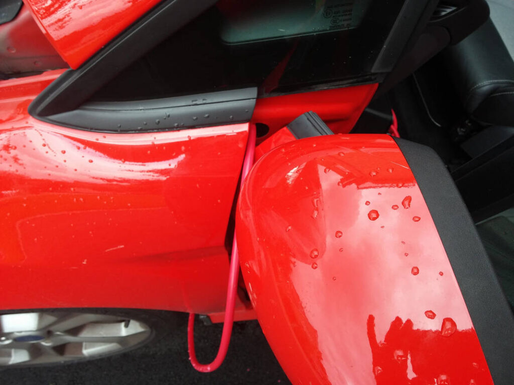
I noticed that the cable was catching on something which was scuffing the insulation as I was pulling it through the hole, but it was minor scuffing and the insulation is very thick. I carefully eased the cable through until I had enough to pass through the wing- there is a gap which provides safe passage to the engine bay, where the cable exits under the bonnet hinge. Before doing this I slid the modified blanking plate with grommet down the cable near the hole, ready to fit when I was done in the engine bay. I passed the cable through the wing and out from under the hinge. I then looped the cable round and fed it under the windscreen cowl, which secured it, neatened it and keeps it out of harms way. The mini ANL fuse holder with battery lead was then attached and secured to the car. The remaining slack from the lead was fed back into the car and the blanking plate with grommet was fitted. Yes, of course the fuse box can still be opened and no, you don’t have to disconnect the lead to get into it 🙂
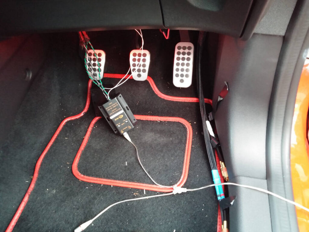
I routed the cables neatly with the help of Tesa 51608 wiring loom tape. It was used to secure the OEM speaker wiring so as to prevent rattles, and to keep my wiring in neat bundles. The amplifier cabinet was fitted to ensure that I cut all cables to the right length. The boot floor was lined (poorly) with automotive grade 6mm closed cell foam to prevent the false floor and cables from rattling. Finally, I prepared and terminated all of the speaker cables. I used ring crimps instead of the traditional fork crimps used on amplifiers because this way the speaker connections will not fall out and risk a short if the terminal screws works loose. This is not a substitute for periodic maintenance; only a failsafe.
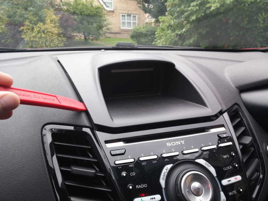
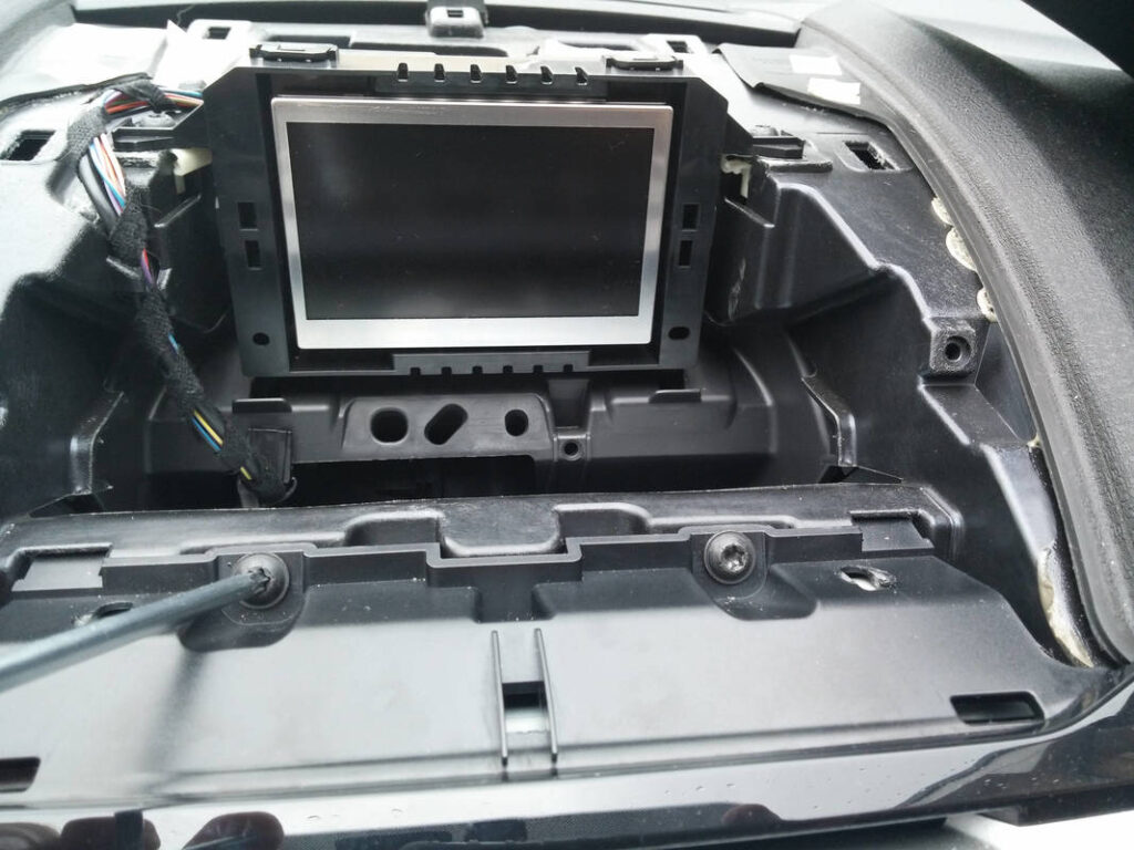
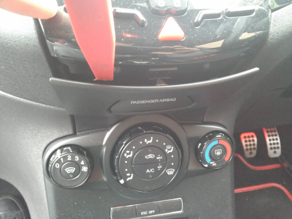
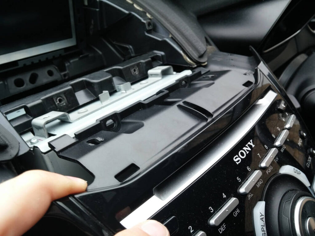
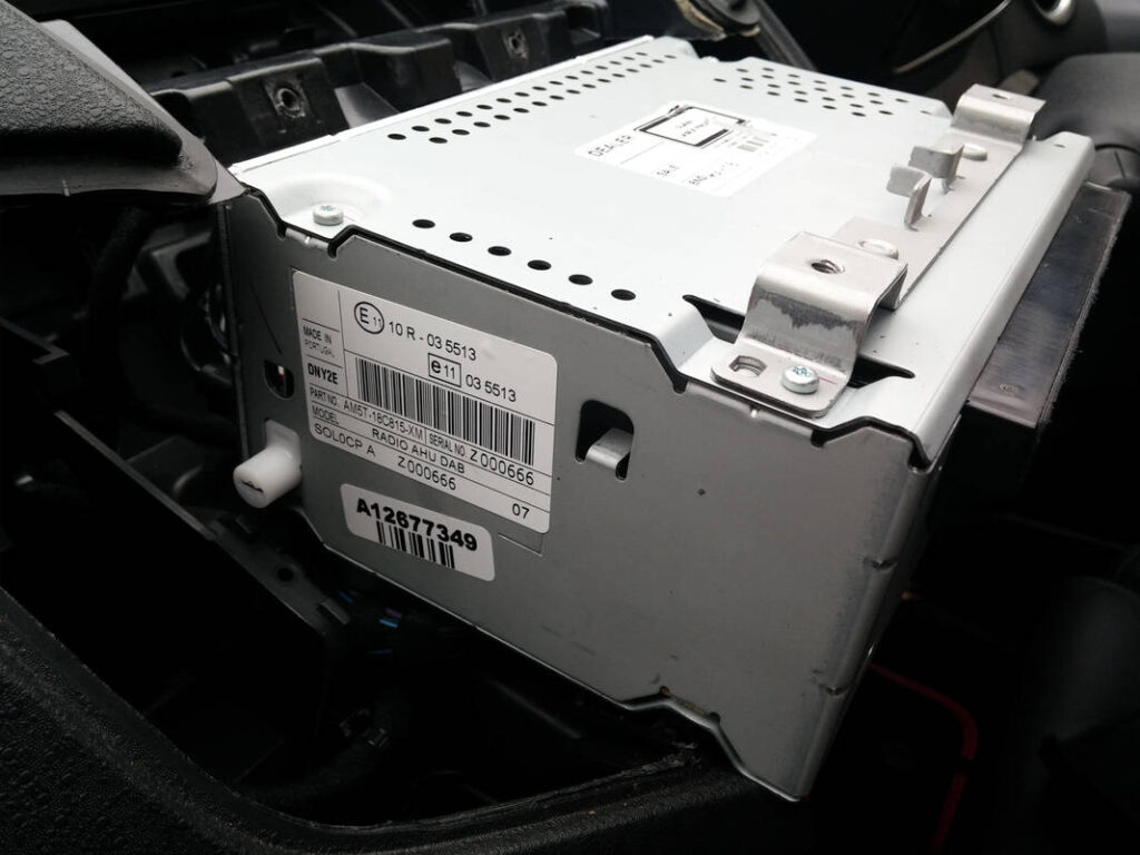
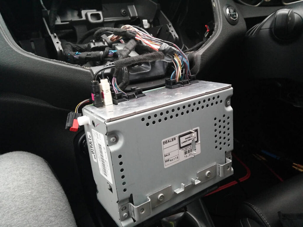
I found this video incredibly helpful and although it wasn’t for the Sony stereo the process was the same. I won’t give a step-by-step description here as it’s all in the video.
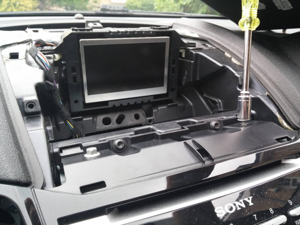
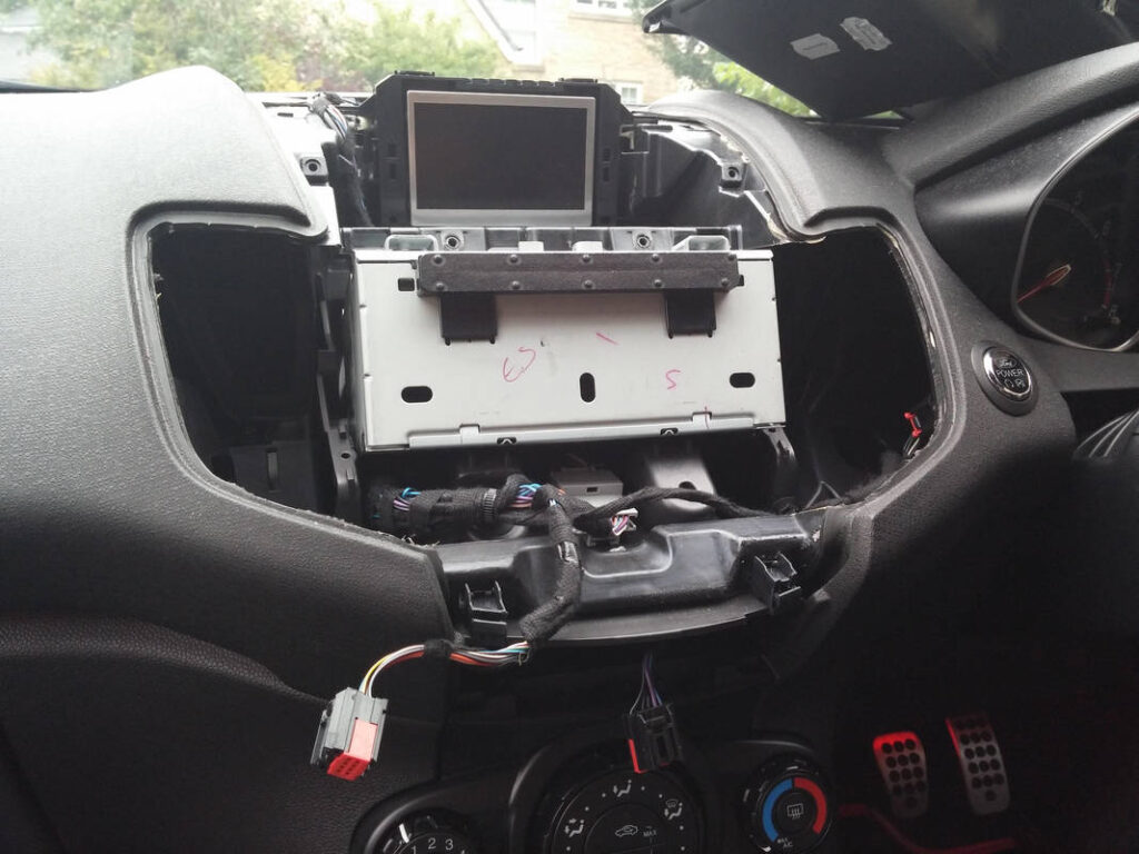
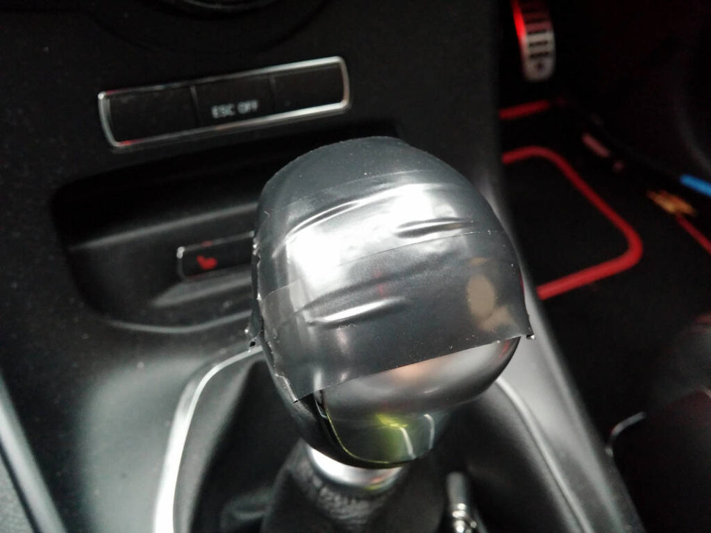
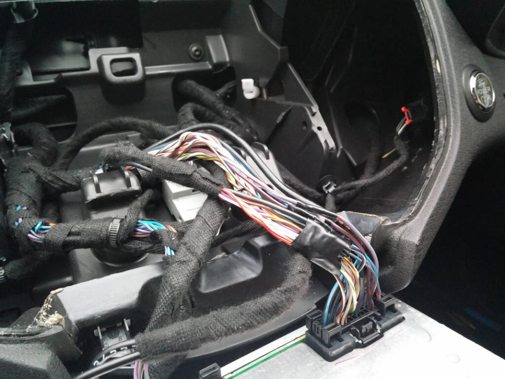
My fascia required quite some force to slide it out. I protected my gearstick with some electrical tape before resting the unit on it. Each speaker connection was tapped behind here and four twisted pairs were run out to the LOCs. The ground was also tapped and run out.
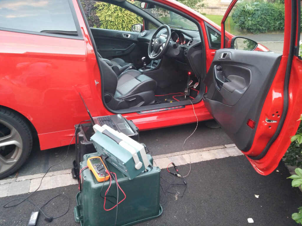
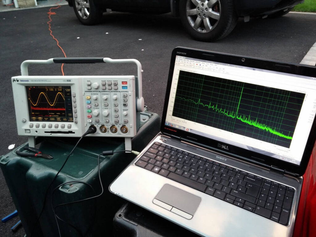
The speaker taps emerge under the driver’s side dash, on JST SM female connectors. The system was measured using a signal generator, osciloscope and laptop with ARTA installed. At the volume notch before hard clipping of the head unit outputs occur (20, clips at >=21) THD+N was measured at 0.43%, and rapidly drops off below this to a fraction of that. I configured the X801-5 to put out 30Wrms to the front and rear speakers and 200Wrms to the Sub. In reality, the system becomes unbearably (painfully) loud by volume notch 14 and I’ve never taken it higher than that with the speakers connected…
I thoroughly enjoyed this project; the scale of this project was far greater than anything I had attempted before. It took ages to plan, there were many challenges, some unexpected, and I am very satisfied with the results of my efforts. I am extremely happy with the performance of Silent Coat- my install hits hard now that I have two subs, yet my mirrors vibrate less than when I had no Silent Coat and the Alpine SWE-815 on it’s own. How much difference has HydroWELD made? I honestly don’t know but I do think the car is warmer now. Wadding makes a sealed speaker enclosure behave as if it were larger, so I will make an educated guess that it has improved the mid-bass response of the front and rear speakers. Unfortunately I don’t know anybody else that has these speakers so can’t make any comparisons! I would like to think that I have preserved the mid-bass response with my DIY foam rings, but again, I have nothing to compare it with. The Pioneer TS-E series are a bit bright for my liking and I had to turn the treble down on the head unit EQ, but following this I think they sound great. I love the stealth nature of my install, looking completely OEM apart from the boot. The boot is useable and practical enough for my needs, and the Alpine sub can quickly and easily be removed if more space is required; the capacity is fairly close to OEM with it removed. Handling and fuel efficiency has not been affected, as much of the weight was traded (eg. spare wheel for sub, false floor for boot liner). I have measured an average of 50mpg on the motorway with tunes blasting; can’t complain with that!